Review Article - Interventional Cardiology (2013) Volume 5, Issue 1
3D fluoroscopy-based imaging in the cardiovascular catheterization laboratory: past, present and future
- Corresponding Author:
- John C Messenger
Division of Cardiology
Interventional Cardiology Section
University of Colorado School of Medicine, Aurora, CO, USA
Tel: +1 720 848 6559
Fax: +1 720 848 7314
E-mail: john.messenger@ucdenver.edu
Abstract
Keywords
3D coronary angiography;3D structural heart guidance;C-arm CT;quantitative coronary angiography
Introduction
The ability to perform catheter-based cardiac procedures has revolutionized cardiovascular care over the past several decades. The continuous development and advancement of technology has allowed for procedures and procedural guidance that would have been hard to imagine just 15 years ago. Along with developments in 3D imaging using transthoracic and transesophageal echocardiography, intravascular imaging using intravascular ultrasound (IVUS), optical coherence tomography (OCT) and intracardiac echocardiography (ICE), a variety of advances have also been made which have allowed for 3D modeling or reconstruction of cardiac structures based on 2D cineangiographic images. The development, evaluation and future potential of 3D cineangiography are presented herein.
2D imaging
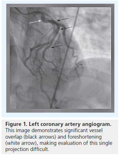
Operators who perform coronary angiography are familiar with the challenges inherent in visualizing the coronary arterial tree in 2D. Due to its high degree of complexity and variability, multiple angiographic acquisitions are generally performed based on different viewing angles in order to fully evaluate the coronary arteries. Even with multiple projections, foreshortening and overlapping of vessels at branch points can result in the need for acquiring additional images from different angiographic views, with the added burden of higher radiation doses and contrast volume received by the patient and operator (Figure 1). The inherent variability and misinterpretation of 2D angiograms has been known and reported on [1–4]. Given that standard angiography relies on obtaining good quality orthogonal views; minimization of overlap and foreshortening of targeted vessels; and maximization of gray level contrast of the vessel lumen compared with surrounding structures, a number of variables can interfere with the reliable assessment of coronary stenoses. Quantitative coronary angiography (QCA) marked the first attempt to standardize the quantification and, therefore, reliability of 2D angiography [5].
Figure 1: Left coronary artery angiogram. This image demonstrates significant vessel overlap (black arrows) and foreshortening (white arrow), making evaluation of this single projection difficult.
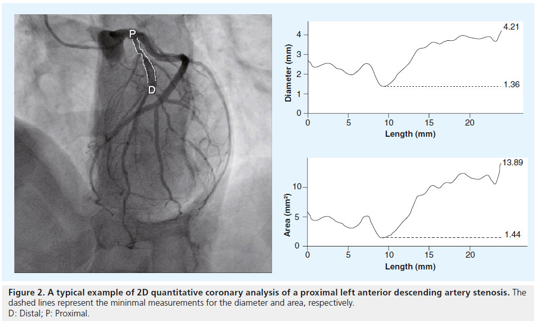
Using automated algorithms that use a known catheter size to calibrate a given image, the size of vessel lumens and stenoses can be analyzed semi-automatically using a variety of QCA software utilities (Figure 2). These utilities tend to give a more objective measure of coronary stenosis than the qualitative assessment made by the angiographer. The main limitations of 2D QCA, in terms of accurate lesion assessment, are that the analyses are dependent on the employed 2D images, which suffer from the different magnification factors inherently associated with the calibration object (i.e., catheter) and targeted arterial segment. Therefore, the use of 2D QCA for the accurate assessment of a 2D image is dependent on the distances of the targeted lesion and the catheter relative to the x-ray detector being the same during image acquisition, which is extremely challenging to achieve.
Rotational angiography
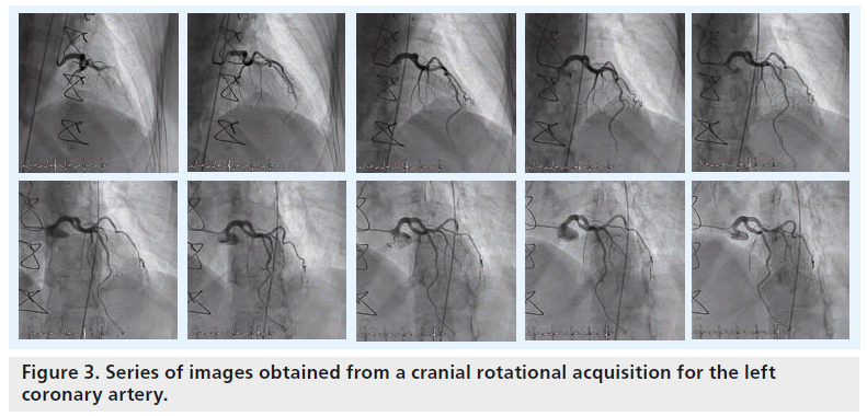
In order to overcome some of the traditional limitations of standard 2D angiography, such as the incomplete evaluation of eccentric lesions and bifurcations, rotational angiography has been developed. Ideally, rotational angiography provides more projection image data as it creates a large number of images of unique views resulting from continuously changing angles in the C-arm rotation (e.g., 180° sweep of the C-arm; Figure 3). This is as opposed to the standard acquisition based on a single static C-arm position. In order to perform an adequate rotational angiogram, the position of the patient’s heart must be centered (i.e., isocentering) with respect to the rotational pathway of the C-arm by setting up the table in the proper location before image acquisition starts. During the isocentering process, the table is first panned by aligning the patient’s heart with the center of fluoroscopic images with anterior–posterior positioning of the flat detector. Afterwards, the height of the table-bed is moved up or down by aligning the patient’s heart with the center of the fluoroscopic image with the flat detector in the lateral position.
Typically, two rotational acquisitions are obtained for the left coronary artery (i.e., one rotation acquires multiple views from right anterior oblique projection (RAO) to left anterior oblique projection (LAO) with a fixed 25° cranial angulation, while the other does so using a RAO to LAO rotation with a fixed 25° caudal angulation). One rotational acquisition is typically employed to acquire multiple views from RAO to LAO with a fixed cranial angle for the right coronary artery (RCA). Alternatively, a dual axis rotational acquisition (i.e., simultaneously changing both LAO/RAO and cranial/caudal projection angulations) has recently been developed that can be used to acquire a single cine run for either the left coronary artery or RCA based on the advanced development of C-arm mechanics.
In addition to the potential benefit of better coronary visualization and assessment, rotational angiography has been demonstrated to reduce both contrast and radiation exposure [6,7]. Given the rotational nature of the acquisition, the coronary arteries are imaged from a continuously changing spectrum of viewing angles, and so the operator is, in theory, less likely to fail to capture the details inherent to complex coronary anatomy.
Rotational angiography is also important in that it allows for the possibility of 3D coronary and cardiac modeling and reconstructions, which will be discussed in the following section in detail. For the sake of 3D reconstruction, the preferred acquisition is commonly performed based on an anterior–posterior 180° acquisition protocol [8,9].
Coronary modeling & reconstruction
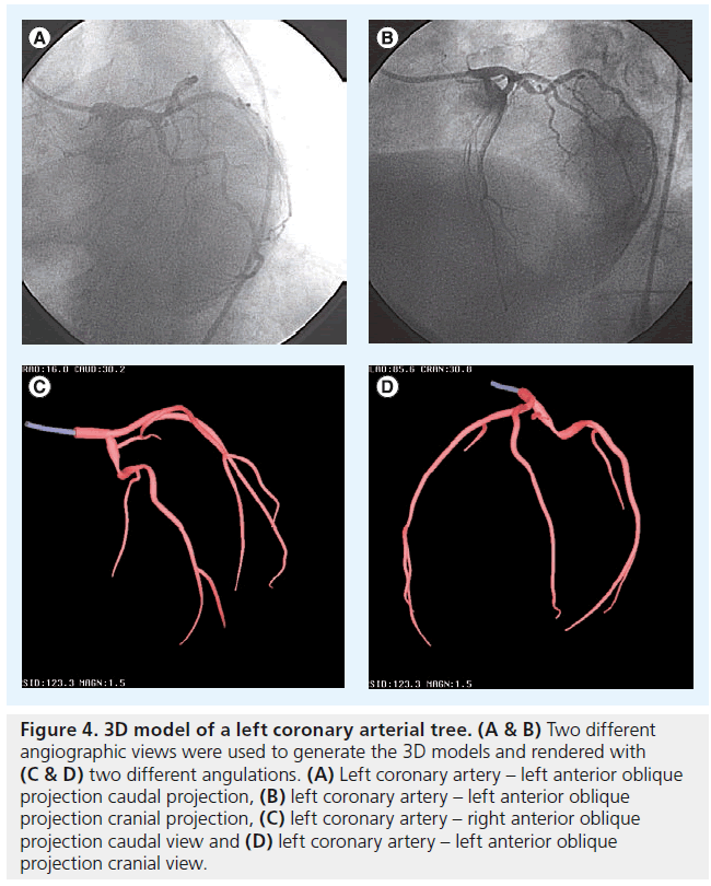
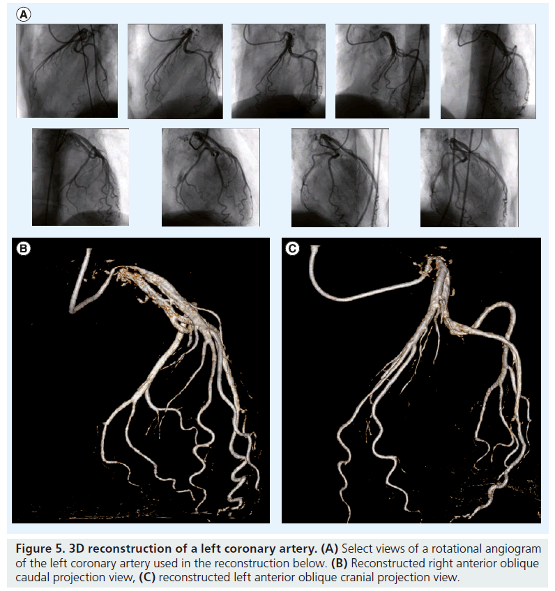
In order to create a 3D image of the coronary arterial tree from 2D angiography, two distinct approaches have been developed. The modeling technique uses a pair of images acquired from two different angiographic views, separated by at least 30° (e.g., orthogonal views; Figure 4) [10]. The cone-beam reconstruction (or C-arm computed tomography [CT]) technique uses a series of images from a rotational C-arm acquisition (Figure 5) [11]. Issues pertinent to these modalities are described in Table 1.
Figure 4: 3D model of a left coronary arterial tree. (A & B) Two different angiographic views were used to generate the 3D models and rendered with (C & D) two different angulations. (A) Left coronary artery – left anterior oblique projection caudal projection, (B) left coronary artery – left anterior oblique projection cranial projection, (C) left coronary artery – right anterior oblique projection caudal view and (D) left coronary artery – left anterior oblique projection cranial view.
Figure 5: 3D reconstruction of a left coronary artery.(A) Select views of a rotational angiogram of the left coronary artery used in the reconstruction below. (B) Reconstructed right anterior oblique caudal projection view, (C) reconstructed left anterior oblique cranial projection view.
| Modeling approach | Reconstruction approach |
|---|---|
| Requires two or more projection images | Requires a 180° rotational acquisition |
| Centerline based | Volumetric based |
| Some user interaction | No user interaction |
| Two views | Multiple views |
| Adapted to most x-ray systems | Currently available only with Philips |
| Healthcare systems | |
| Currently in clinical use | Needs implementation |
Table 1. Comparison of 3D coronary modeling versus reconstruction.
The modeling technique provides detailed information regarding the course of a vessel with approximated circular or elliptical vessel contours of the coronary tree, which results in a lack of detailed luminal cross-sectional information. This allows the operator to predict optimal views (i.e., minimizing vessel overlapping and foreshortening with respect to any arterial segment or stenotic lesion) without exposing the patient to additional contrast or radiation. By contrast, the 3D reconstruction technique creates a full-volume data set from multiple cone-beam projection images that is not dissimilar to multislice CT (MSCT). In so doing, 3D intravascular coronary analysis, such as vessel diameter, lumen diameter and degree of stenosis, can be performed, offering a less invasive alternative to invasive imaging technologies such as IVUS and OCT.
3D proof of concept & comparison with 2D QCA
Given the limitations of 2D coronary cineangiography and traditional 2D QCA, it is apparent that the 3D representation of cardiac or coronary structures based on 2D images can optimize quantitative coronary evaluations and facilitate image-guided interventions. For instance, the resultant 3D reconstructions can truly model complex bifurcation angles, anomalous coronary origins, and eccentric stenoses. Practically, this allows the operator to better interpret complex anatomy, choose optimal guide catheters and intracoronary equipment, size lesions and reference vessels for optimal stent outcomes, and evaluate the acute procedural outcomes of percutaneous coronary interventions.
It has been demonstrated that a 3D model of the coronary arteries derived from conventional MSCT can be imported into the x-ray imaging system in the cardiovascular catheterization laboratory as a live overlay during fluoroscopic acquisition to guide percutaneous coronary interventions [12,13]. However, the true goal is to be able to generate a CT-like image at the time of coronary angiography while the patient is on the table, and then use those 3D images to guide the procedure without obtaining a preprocedure CT.
Initial attempts at 3D modeling required a high degree of input from the angiographer, using either single plane [14] or biplane [15] imaging systems. These studies essentially represented a proof of concept of an evolving technology. In these studies, so-called phantom models (inanimate objects with radiodense curvilinear patterns) were employed in order to validate the accuracy of the 3D modeling method using a known and easy-to-quantify physical model. The validation algorithms were then employed in the evaluation of coronary angiograms. The modeling techniques generate 3D vessel centerline and circular or elliptical vessel contours, resulting in a 3D surface-based representation of the coronary arterial tree [16,17]. While these studies demonstrated the overall accurate geometry of a 3D geometric model, the current processing methods were not considered to be optimal for clinical use due to the need for significant user interaction with a workstation outside the laboratory.
In an attempt to make 3D reconstruction more automated and independent of the angiographer, another technique which used a continuous 180° image acquisition was developed and tested in humans [8,18]. This demonstrated good reliability in terms of vessel sizing (in largely normal coronary arterial beds), and the promise of better evaluation of bifurcation points. There was some concern regarding false-positive coronary stenoses, and the general conclusion was that this method served as a reasonable adjunct to, but not as a replacement of, standard coronary angiography.
3D QCA compared with IVUS & fractional flow reserve
Part of the allure of 3D coronary imaging would be the ability to model structural and physiologic properties of the artery without using invasive tools such as IVUS, OCT and fractional flow reserve (FFR). Conventional MSCT has been proven to clearly demonstrate vessel size, atheroma volume, plaque density and degree of stenosis [19,20]. Should similar imaging quality be able to be obtained with 3D coronary reconstructions, one could make the argument that such imaging could supplant the aforementioned, more invasive technologies, as it is without the risks inherent to an intracoronary procedure.
Attempts have been made to compare both 2D and 3D QCA with both IVUS [21–23] and FFR [24]. These studies demonstrated that 3D QCA can predict a minimum luminal area of left main stenoses <6 mm2, as measured by IVUS, and that both vessel length [22] and luminal diameter and area [23] correlate reasonably well with IVUS measurements. However, whether such measurements could supplant IVUS intraprocedurally remains an open and unstudied question. Similarly, 3D minimum luminal area and 2D minimum luminal diameter predictions correlated best with an FFR of ≤0.75, but both correlations were modest and not sufficient to be used in place of FFR.
While MSCT has been shown to be comparable with IVUS, its ability to determine physiologic significance, such as is defined by FFR, is much more questionable. Therefore, the goal of 3D coronary modeling would be to achieve the accuracy obtained with MSCT, but with less contrast and radiation use. This would then represent the optimal imaging scenario for the evaluation of complex coronary stenoses.
▪ Currently available commercial tools for 3D coronary modeling & reconstruction
The 3D processing tools that have become commercially available are mainly for 3D coronary modeling based on a pair of angiographic images and for 3D reconstruction based on images obtained from a series of rotational 180° projections. These tools are provided by several vendors, as described in Table 2. Each vendor has either developed its own custom software integration technology to render 3D data sets, or has incorporated thirdparty vendors to complete the task (Figure 6). Philips Healthcare (Best, The Netherlands) has created and validated its own custom integrated 3D modeling and 3D reconstruction solutions (i.e., Allura 3D-coronary angiography and Allura 3D-rotational angiography, respectively) [8,14]. Two third-party software solutions are available for integration with other manufacturers’ systems. Pie Medical Imaging (Maastricht, The Netherlands) Coronary Artery Analysis Software QCA-3D [25,26] and Paieon, Inc.’s (Rosh Ha’ayin, Israel) IC-PRO™ [27,28] provide 3D coronary modeling solutions that were validated based on phantom and clinical data. These validation studies have demonstrated good accuracy when reconstructing phantom models. The IC-PRO package can calculate bifurcation parameters to analyze the geometric and angle changes that may occur after stenting bifurcation lesions. Pie Medical Imaging Coronary Artery Analysis Software QCA-3D package allows a stenotic segment to be identified by clicking proximally and distally to the lesion and defining a common landmark in both selected views. The computed 3D artery segment model is then rendered along with luminal area and diameter graphs. Length, minimum luminal diameter and stenosis degree measurements are supported. The Philips Healthcare 3D-coronary angiography and 3D-rotational angiography tools take rotational angiographic images as input, while Pie Medical Imaging and Paieon, Inc. use a pair of images acquired via the standard angiographic imaging technique.
| Manufacturer | 3D technology name | Acquisition type | 3D analysis |
|---|---|---|---|
| Philips Healthcare | Allura 3D-coronary angiography | Fixed or rotational | Modeling |
| Philips Healthcare | Allura 3D-rotational angiography | Rotational | Reconstruction |
| Paieon, Inc. | IC-PRO† | Fixed | Modeling |
| Pie Medical Imaging | CAAS QCA-3D‡ | Fixed | Modeling |
Table 2. 3D coronary modeling and reconstruction solutions.
The goal in using these various 3D technologies would be to allow for the creation of 3D geometry of patient-specific coronary arterial trees. This would not only allow for the prediction of optimal gantry angulation for better visualization of vessels (such as bifurcations) on angiographic images [27], but would also allow for accurate sizing of lesions and stent length and diameter [28].
3D image guidance for coronary interventions
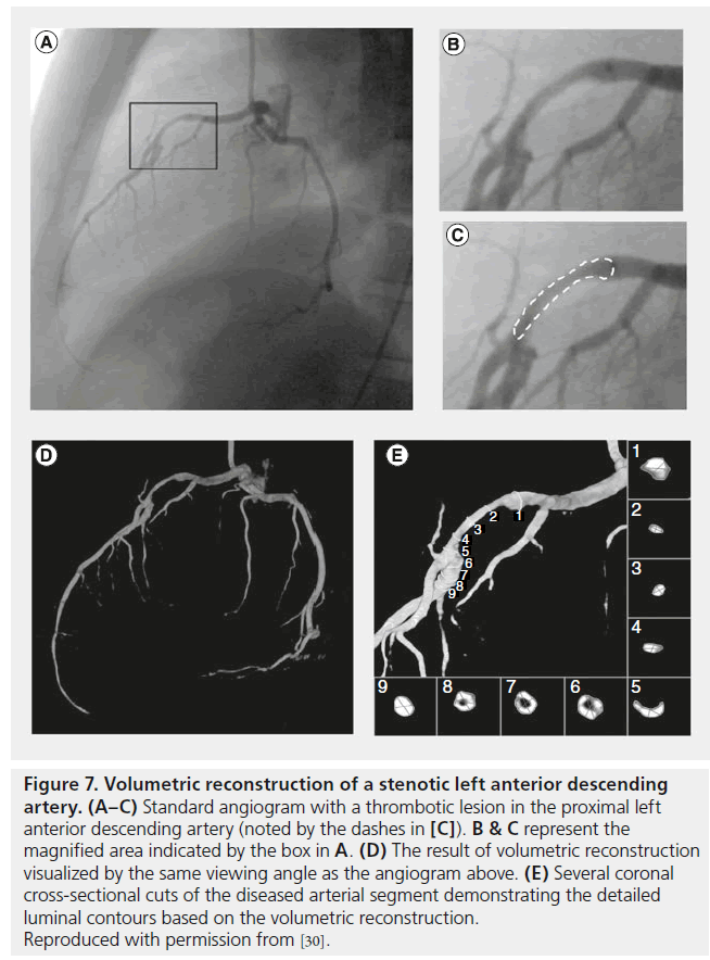
Although the use of 3D coronary modeling or reconstruction has not specifically been proven beneficial in guiding coronary interventions in clinical trials, several studies have shown the potential benefits of this technology. Our group has demonstrated the ability to model the 3D patient-specific coronary tree and intracoronary devices [29], to visualize intracoronary thrombus (Figure 7) [30], and to model the effect of coronary stents on arterial geometry [31]. Furthermore, vessel sizing and stent selection have been shown to have the potential to be improved by the use of 3D imaging guidance [32]. Such promising early demonstration work suggests that 3D coronary modeling and reconstruction has the potential to further impact percutaneous coronary evaluation and intervention. The degree to which coronary modeling is adopted broadly will likely depend on the degree of automation, anatomic accuracy and reduction in contrast and radiation exposure that can be achieved with the various modeling tools.
Figure 7: Volumetric reconstruction of a stenotic left anterior descending artery. (A–C) Standard angiogram with a thrombotic lesion in the proximal left anterior descending artery (noted by the dashes in [C]). B & C represent the magnified area indicated by the box in A. (D) The result of volumetric reconstruction visualized by the same viewing angle as the angiogram above. (E) Several coronal cross-sectional cuts of the diseased arterial segment demonstrating the detailed luminal contours based on the volumetric reconstruction. Reproduced with permission from [30].
Peripheral arterial interventions
There seems to be less interest in 3D modeling of peripheral arterial vasculature than of the coronary tree. This may in part be related to the less complex anatomy typically encountered in a lower extremity or renal intervention, when compared with coronary evaluation. Two areas that have been targeted are intracranial and abdominal aortic aneurysm (AAA) evaluations.
The intracranial arterial tree is quite complex and tortuous, with many sites of overlap that can be difficult to fully evaluate with traditional 2D imaging. The evaluation of the angulation and sizing of an AAA, as well as its orientation to the common iliac and renal arteries, is critical to the successful placement of an aortic graft. These two areas have received a fair amount of attention from the developers of 3D modeling algorithms.
By far, the most well validated and studied technology in the periphery is the Siemens (Munich, Germany) DynaCT, which has demonstrated utility in guiding a variety of intracranial diagnostic and imaging procedures. Specifically, intracranial aneurysm coiling, volumetric cranial reconstruction for the purpose of evaluating subarachnoid hemorrhage, guiding of complex carotid stent procedures, and the evaluation of intracranial in-stent restenosis have all been demonstrated [33–36]. Moreover, it has compared well with MSCT in evaluating and planning endovascular aortic repair procedures for aortic aneurysms [37–39].
In the future, peripheral applications will likely benefit from the advancement of technologies designed for coronary evaluation. At the moment, the two areas of interest for the peripheral endovascular specialist appear to remain intracranial and AAA interventions.
Structural heart interventions
▪ C-arm CT
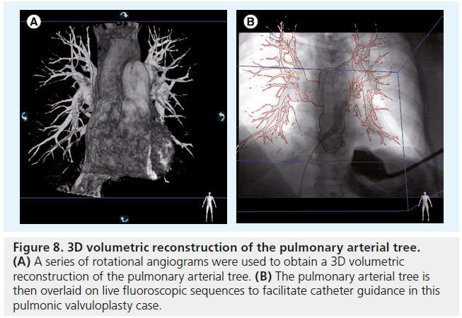
Beyond coronary modeling, the advent of conebeam reconstruction, or C-arm CT, holds great promise for guiding catheter-based structural heart interventions. This technology involves the rotational acquisition of cardiac soft tissue data, which then generates a model of the heart structures that can be overlaid on live fluoroscopic images (Figure 8) [9]. This allows operators to understand where they are in space, and to facilitate catheter movements and device deployments.
Figure 8: 3D volumetric reconstruction of the pulmonary arterial tree. (A) A series of rotational angiograms were used to obtain a 3D volumetric reconstruction of the pulmonary arterial tree. (B) The pulmonary arterial tree is then overlaid on live fluoroscopic sequences to facilitate catheter guidance in this pulmonic valvuloplasty case.
▪ Challenges to 3D-image generation Several challenges are particular to the generation of 3D images of the beating heart and adjacent structures. The first challenge is cardiac motion. In order to overcome this, an ECG signal is acquired with the series of rotational angiograms. The images can then be retrospectively gated to one consistent time point in the cardiac cycle, similar to methods used in cardiac CT [40]. In order to obtain optimal images, a high frame rate (up to 50 frames/s), slow heart rate (as in traditional cardiac CT), and slow gantry movement with 20–30-s acquisition times are ideal.
Secondly, contrast opacif ication of the large cardiac chambers presents a significant challenge [9]. In order to overcome this, it has been suggested that the contrast be given via a catheter proximal to the heart, such as the inferior vena cava. This allows for mixing of contrast with the blood and helps to minimize the issue of contrast streaming. Moreover, a test dose is administered in order to set the timing of the injection such that all relevant structures are imaged. This is particularly important with respect to left-sided contrast filling. Due to the heterogeneity of cardiac output, the time at which the left atrium, left ventricle and aorta may fill can vary significantly from one patient to the next.
Finally, as contrast makes its way from the right side of the heart to the left, it becomes relatively dilute in left-sided structures. In order to overcome this relative opacification issue, it may be of benefit to give a higher rate of contrast early in the injection, followed by a slower maintenance rate and even possibly a saline infusion for the remainder of the injection.
▪ Procedural guidance
One must then consider the advantages of intraprocedural C-arm CT versus using a previously obtained cardiac CT and simply overlaying those images. Several potential advantages include sparing the patient an additional visit and radiation exposure from the cardiac CT, likely less contrast use, fewer troubles with image registration and integration with fluoroscopy, and the ability to directly compare repeat images at the conclusion of the procedure.
C-arm CT has been demonstrated to be useful in a variety of cardiac-specific procedures, including pulmonary vein isolation [41], pulmonary vein stenting [42] and aortic valve implantation [43–47].
3D guidance of transaortic valve replacement has been described in the context of case reports [45,46]. Paieon’s C-THV software has been shown to be of assistance in determining the optimal viewing angles for valve implantation [43,44] and has been useful in assessing the natural movement of the Edwards SAPIEN™ (Edwards Lifesciences, CA, USA) valve in the course of implantation [47]. MSCT is now being used routinely to evaluate the aortic valve annulus, and data from these protocols can be incorporated into fluoroscopy systems, such that segmented views of the aorta are available to guide valve implantation [48,49]. To date, there are no data on whether such techniques affect procedural success or patient-specific outcomes.
▪ Available tools
Currently available imaging programs include the integrated Philips Healthcare HeartNavigator and Siemens syngo DynaCT [45,46], as well as standalone third party solutions by Pie Medical Imaging (A-Valve) and Paieon (C-THV) [43,44,47]. Similar to coronary reconstructions, these tools have been shown to be viable as a proof of concept, but have yet to be rigorously validated or studied in a context where relevant patient outcomes could be evaluated.
Challenges
The current generation of 3D technologies available for use in the cardiovascular catheterization laboratory is exciting and promising, but early in the development phase. To some degree, 3D coronary modeling and reconstruction have struggled to gain traction as reliable, day-to-day tools for clinical use. While it demonstrates promise, the inability to create fully automated reconstructions in real time is a major limitation. That, in combination with readily available, easy-to-use technologies such as IVUS and OCT, means that further refinement of these technologies will be required before routine use is seen.
The implementation of C-arm CT shows significant promise, particularly with respect to offering an alternative to integrating previously obtained CT images with live fluoroscopy, which is burdened by significant technical challenges related to registering the CT data with the live images. The challenges inherent to C-arm CT center around the ability to fill the relevant cardiac and pulmonary structures with contrast agents in a way that minimizes contrast streaming and phase delay such that the images obtained are accurate and optimized for procedural guidance.
Conclusion
3D modeling and reconstruction of coronary arteries and structural heart defects offers signif icant potential for guidance of interventional procedures. Whether these technologies will ultimately overtake such currently available tools as IVUS, OCT, ICE, 3D transesophageal echocardiogram and MSCT remains an open question. Broad adoption of these technologies will ultimately depend on the ability to automate the analyses, make integration of the 3D model with the realtime fluoroscopic views straightforward, and to reduce the overall contrast and radiation exposure of the patient, when compared with these more conventional techniques. Clinical trials designed to assess for the impact of these technologies on decision-making and relevant patient outcomes are needed in order to move the field forward.
Future perspective
Real-time 3D modeling of the coronary arteries and structural heart anomalies holds the potential to overtake a number of currently available, but invasive, cardiovascular catheterization laboratory tools such as IVUS, OCT, ICE and 3D transesophageal echocardiogram. Moreover, C-arm CT could eliminate the need for a preprocedure MSCT, significantly reducing the amount of radiation, contrast exposure and hospital visits for the patient.
With further improvements in automation and validation compared with IVUS and/or OCT, 3D coronary modeling should provide a means for the interventionalist to understand complex anatomy, noninvasively evaluate indeterminate coronary stenoses and optimize stent choice, placement and postimplant evaluation.
C-arm CT for the guidance of structural heart interventions is relatively more advanced and ‘ready for primetime’. The images are relatively easy to obtain and implement in real time, and offer significant advantages in terms of procedural guidance in complex anatomy. It is not hard to imagine a future where routine C-arm CT overlays are used to routinely guide complex structural and congenital heart disease interventions, eliminating the need for more invasive and expensive technologies, such as ICE and 3D transesophageal echocardiogram.
To date, very limited clinical trial data are available to assess the clinical impact of 3D modeling and reconstruction algorithms. Our feeling is that, in order to move the field forward, it will be important for the developers of these technologies to sponsor relevant clinical trials to assess not only the feasibility of 3D rendering, but more importantly the impact on clinical decision-making. It would also be important to ultimately assess the impact such technologies might have on pertinent patient outcomes, such as enhancing procedural success rates and limiting complications.
Financial & competing interests disclosure
JD Carroll reports consulting fees, research support, and patent royalties from Philips Healthcare Medical. The authors have no other relevant affiliations or financial involvement with any organization or entity with a financial interest in or financial conflict with the subject matter or materials discussed in the manuscript apart from those disclosed.
No writing assistance was utilized in the production of this manuscript.
Executive summary
Conventional coronary angiography
▪ Angiography is routinely used and understood by all invasive cardiologists.
▪ This technology is limited by its 2D nature, vessel foreshortening and overlap.
▪ Angiography is associated with suboptimal views of vessel bifurcations and eccentric lesions.
Quantitative coronary angiography
▪ Quantitative coronary angiography quantifies and reduces inter- and intra-observer variability with respect to coronary stenosis evaluation.
▪ Quantification is labor intensive and not routinely used in clinical work.
▪ Quantitative coronary angiography suffers from the same limitations noted above for conventional coronary angiography.
3D coronary angiography
▪ 3D angiography offers the possibility of supplanting the need for coronary computed tomography, intravascular ultrasound and optical coherence tomography in certain circumstances.
▪ This technology is still in the developmental phase.
▪ 3D angiography is limited by the need for offline processing.
▪ 3D angiography has not been validated against more conventional technologies.
C-arm computed tomography: 3D guidance for structural heart disease interventions
▪ C-arm computed tomography offers the possibility of supplanting the need for cardiac computed tomography, intracardiac echocardiography and transesophageal echocardiogram in certain circumstances.
▪ This technology is still in the developmental phase.
▪ C-arm computed tomography has been validated in guiding a subset of structural heart interventions.
References
Papers of special note have been highlighted as:
▪ of considerable interest
- White CW, Wright CB, Doty DB et al. Does visual interpretation of the coronary arteriogram predict the physiologic importance of a coronary stenosis? N. Engl. J. Med. 310(13), 819–824 (1984).
- Detre KM, Wright E, Murphy ML, Takaro Observer agreement in evaluating coronary angiograms. Circulation 52(6), 979–986 (1975).
- Zir LM, Miller SW, Dinsmore RE, Gilbert JP, Harthorne JW. Interobserver variability in coronary angiography. Circulation 53(4), 627–632 (1976).
- DeRouen TA, Murray JA, Owen W. Variability in the analysis of coronary arteriograms. Circulation 55(2), 324–328 (1977).
- Garrone P, Biondi-Zoccai G, Salvetti I et al. Quantitative coronary angiography in the current era: principles and applications. Interv. Cardiol. 22(6), 527–536 (2009).
- Maddux JT, Wink O, Messenger JC et al. Randomized study of the safety and clinical utility of rotational angiography versus standard angiography in the diagnosis of coronary artery disease. Catheter. Cardiovasc. Interv. 62(2), 167–174 (2004).
- Klein AJ, Garcia JA, Hudson PA et al. Safety and efficacy of dual-axis rotational coronary angiography vs. standard coronary angiography. Catheter. Cardiovasc. Interv.77(6), 820–827 (2011).
- Neubauer AM, Garcia JA, Messenger JC et al. Clinical feasibility of a fully automated 3D reconstruction of rotational coronary x-ray angiograms. Circ. Cardiovasc. Interv. 3(1), 71–79 (2010).
- Schwartz JG, Neubauer AM, Fagan TE, Noordhoek NJ, Grass M, Carroll JD. Potential role of three-dimensional rotational angiography and C-arm CT for valvular repair and implantation. Int.J. Cardiovasc. Imaging 27(8), 1205–1222(2011).
- Chen SJ, Schafer D. Three-dimensional coronary visualization, part 1: modeling. Cardiol. Clin. 27(3), 433–452 (2009).
- Schoonenberg G, Neubauer A, Grass M. Three-dimensional coronary visualization, part 2: 3D reconstruction. Cardiol. Clin. 27(3), 453–465 (2009).
- Hecht HS. Applications of multislice coronary computed tomographic angiography to percutaneous coronary intervention: how did we ever do without it? Catheter Cardiovasc. Interv. 71(4), 490–503(2008).
- Garcia JA, Bhakta S, Kay J et al. Online multislice computed tomography interactive overlay with conventional x-ray: a new and advanced imaging fusion concept. Int. J. Cardiol. 133(3), e101–105 (2009).
- Messenger JC, Chen SY, Carroll JD, Burchenal JE, Kioussopoulos K, Groves BM. 3D coronary reconstruction from routine single-plane coronary angiograms: clinical validation and quantitative analysis of the right coronary artery in 100 patients. Int. J. Card. Imaging 16(6), 413–427 (2000).
- Wellnhofer E, Wahle A, Mugaragu I, Gross J, Oswald H, Fleck E. Validation of an accurate method for three-dimensional reconstruction and quantitative assessment of volumes, lengths and diameters of coronary vascular branches and segments from biplane angiographic projections. Int. J. Card. Imaging 15(5), 339–353; discussion 355–336 (1999).
- Chen SJ, Carroll JD. 3D reconstruction of coronary arterial tree to optimize angiographic visualization. IEEE Trans. Med. Imaging 19(4), 318–336 (2000).
- Movassaghi B, Rasche V, Grass M, Viergever MA, Niessen WJ. A quantitative analysis of 3D coronary modeling from two or more projection images. IEEE Trans. Med. Imaging 23(12), 1517–1531 (2004).
- Garcia JA, Chen SY, Messenger JC et al. Initial clinical experience of selective coronary angiography using one prolonged injection and a 180° rotational trajectory. Catheter Cardiovasc. Interv. 70(2), 90–196 (2007).
- Hecht HS, Roubin G. Usefulness of computed tomographic angiography guided percutaneous coronary intervention. Am. J. Cardiol. 99(6), 871–875 (2007).
- Schroeder S, Kopp AF, Baumbach A et al. Noninvasive detection and evaluation of atherosclerotic coronary plaques with multislice computed tomography. J. Am. Coll. Cardiol. 37(5), 1430–1435 (2001).
- Porto I, Dato I, Todaro D et al. Comparison of two- and three-dimensional quantitative coronary angiography to intravascular ultrasound in the assessment of intermediate left main stenosis. Am. J. Cardiol. 109(11), 1600–1607 (2012).
- Tu S, Huang Z, Koning G, Cui K, Reiber JH. A novel three-dimensional quantitative coronary angiography system: in vivo comparison with intravascular ultrasound for assessing arterial segment length. Catheter Cardiovasc. Interv. 76(2), 291–298 (2010).
- Tu S, Xu L, Ligthart J et al. In vivo comparison of arterial lumen dimensions assessed by coregistered 3D quantitative coronary angiography, intravascular ultrasound and optical coherence tomography. Int. J. Cardiovasc. Imaging 28(6),1315–1327 (2012).
- Yong AS, Ng AC, Brieger D, Lowe HC, Ng MK, Kritharides L. Three-dimensional and two-dimensional quantitative coronary angiography, and their prediction of reduced fractional flow reserve. Eur. Heart J. 32(3), 345–353 (2011).
- Schuurbiers JC, Lopez NG, Ligthart J et al. In vivo validation of CAAS QCA-3Dcoronary reconstruction using fusion of angiography and intravascular ultrasound (ANGUS). Catheter Cardiovasc. Interv. 73(5), 620–626 (2009).
- Ramcharitar S, Daeman J, Patterson M et al. First direct in vivo comparison of two commercially available three-dimensional quantitative coronary angiography systems. Catheter Cardiovasc. Interv. 71(1),44–50 (2008).
- Girasis C, Serruys PW, Onuma Y et al. 3-Dimensional bifurcation angle analysis in patients with left main disease: a substudy of the SYNTAX trial (SYNergy between percutaneous coronary intervention with TAXus and cardiac surgery). JACC Cardiovasc. Interv. 3(1), 41–48 (2010).
- Rittger H, Schertel B, Schmidt M, Justiz J, Brachmann J, Sinha AM. Three-dimensional reconstruction allows accurate quantification and length measurements of coronary artery stenoses. EuroIntervention 5(1), 127–132 (2009).
- Chen SY, Carroll JD, Messenger JC. Quantitative analysis of reconstructed 3D coronary arterial tree and intracoronary devices. IEEE Trans. Med. Imaging 21(7), 724–740 (2002).
- Schoonenberg GA, Garcia JA, Carroll JD. Left coronary artery thrombus characterized by a fully automatic three-dimensional gated reconstruction. Catheter Cardiovasc. Interv.74(1), 97–100 (2009).
- Liao R, Green NE, Chen SY et al. Three-dimensional analysis of in vivo coronary stent – coronary artery interactions.Int. J. Cardiovasc. Imaging 20(4),305–313 (2004).
- Gollapudi RR, Valencia R, Lee SS, Wong GB, Teirstein PS, Price MJ. Utility of three-dimensional reconstruction of coronary angiography to guide percutaneous coronary intervention. Catheter Cardiovasc. Interv.69(4), 479–482 (2007).
- White PM, Gilmour JN, Weir NW, Innes B, Sellar RJ. AngioCT in the management of neurointerventional patients: a prospective, consecutive series with associated dosimetry and resolution data. Neuroradiology 50(4), 321–330 (2008).
- Doelken M, Struffert T, Richter G et al. Flat-panel detector volumetric CT for visualization of subarachnoid hemorrhage and ventricles: preliminary results compared with conventional CT. Neuroradiology 50(6), 517–523 (2008).
- Mordasini P, Al-Senani F, Gralla J, Do DD, Brekenfeld C, Schroth G. The use of flat panel angioCT (DynaCT) for navigation through a deformed and fractured carotid stent. Neuroradiology 52(7), 629–632 (2010).
- Moskowitz SI, Kelly ME, Haynes J, Fiorella D. DynaCT evaluation of in-stent restenosis following Wingspan stenting of intracranial stenosis. J. Neurointerv. Surg. 2(1), 2–5 (2010).
- Eide KR, Odegard A, Myhre HO, Lydersen S, Hatlinghus S, Haraldseth O. DynaCT during EVAR – a comparison with multidetector CT. Eur. J. Vasc. Endovasc. Surg. 37(1),23–30 (2009).
- Eide KR, Odegard A, Myhre HO, Hatlinghus S, Haraldseth O. DynaCT in pretreatment evaluation of aortic aneurysm before EVAR. Eur. J. Vasc. Endovasc. Surg. 42(3),332–339 (2011).
- Nordon IM, Hinchliffe RJ, Malkawi AH et al. Validation of DynaCT in the morphological assessment of abdominal aortic aneurysm for endovascular repair. J. Endovasc. Ther. 17(2), 183–189 (2010).
- Lauritsch G, Boese J, Wigstrom L, Kemeth H, Fahrig R. Towards cardiac C-arm computed tomography. IEEE Trans. Med. Imaging 25(7), 922–934 (2006).
- Nolker G, Asbach S, Gutleben KJ et al. Image-integration of intraprocedural rotational angiography-based 3D reconstructions of left atrium and pulmonary veins into electroanatomical mapping: accuracy of a novel modality in atrial fibrillation ablation. J. Cardiovasc. Electrophysiol. 21(3), 278–283 (2010).
- Krishnaswamy A, Tuzcu EM, Kapadia SR. Three-dimensional computed tomography in the cardiac catheterization laboratory. Catheter Cardiovasc. Interv. 77(6),860–865 (2011).
- Dvir D, Kornowski R. Percutaneous aortic valve implantation using novel imaging guidance. Catheter Cardiovasc. Interv. 76(3), 450–454 (2010).
- Tzikas A, Schultz C, Van Mieghem NM, de Jaegere PP, Serruys PW. Optimal projection estimation for transcatheter aortic valve implantation based on contrast-aortography: validation of a Prototype Software. Catheter Cardiovasc. Interv. 76(4), 602–607 (2010).
- Kempfert J, Noettling A, John M, Rastan A, Mohr FW, Walther T. Automatically segmented DynaCT: enhanced imaging during transcatheter aortic valve implantation. J. Am. Coll. Cardiol. 58(25), e211 (2011).
- Maeda K, Kuratani T, Torikai K, Shimamura K, Sawa Y. Transcatheter aortic valve replacement using DynaCT. J. Card. Surg. 27(5), 551–553 (2012).
- Dvir D, Lavi I, Eltchaninoff H et al. Multicenter evaluation of Edwards SAPIEN positioning during transcatheter aortic valve implantation with correlates for device movement during final deployment. JACC Cardiovasc. Interv. 5(5),563–570 (2012).
- Jilaihawi H, Kashif M, Fontana G et al. Cross-sectional computed tomographic assessment improves accuracy of aortic annular sizing for transcatheter aortic valve replacement and reduces the incidence of paravalvular aortic regurgitation. J. Am. Coll. Cardiol. 59(14), 1275–1286 (2012).
- Schoenhagen P, Numburi U, Halliburton SS et al. Three-dimensional imaging in thecontext of minimally invasive and transcatheter cardiovascular interventions using multi-detector computed tomography: from pre-operative planning to intra-operative guidance. Eur. Heart J. 31(22), 2727–2740 (2010).
▪▪ Feasibility study demonstrating the possiblity of creating 3D volume reconstructions from 2D imagery.
▪▪ Comprehensive review of 3D coronary modeling technique.
▪▪ Comprehensive review of 3D coronary reconstruction technique.
▪▪ Proof of concept and feasibility of 3D coronary modeling.
▪▪ Interesting study of the challenges inherent to comparing 3D measurements with more well-validated imaging, such as intravascular ultrasound and optical coherence tomography.
▪▪ Demonstration of the potential utility of 3D imaging in guiding intraprocedural decision-making.
▪▪ Interesting proof-of-concept study demonstrating the use of intraprocedural cardiovascular reconstruction for aiding cardiovascular catheterization laboratory procedures.
▪ ▪ Informative review of the use of CT imaging to plan and execute catheter based procedures.
