Review Article - Imaging in Medicine (2010) Volume 2, Issue 6
Improving high-field MRI using parallel excitation
William A Grissom†1, Laura Sacolick1 & Mika W Vogel11GE Global Research, Freisinger Landstrasse 50, D-85748 Garching bei München, Germany
- Corresponding Author:
- William A Grissom
GE Global Research
Freisinger Landstrasse 50
D-85748 Garching bei München, Germany
E-mail: wgrissom@gmail.com
Abstract
MRI at high magnetic field strengths promises to deliver clearer images of the body’s structure and function. However, high-field MRI currently faces several substantial engineering challenges before it can be considered robust and safe enough for routine clinical use. Challenges include increased radiofrequency (RF) energy deposition that can create unsafe patient heating, large main field inhomogeneities that prevent functional neuroimaging in the lower brain and inhomogeneous RFs transmit fields that cause spatially varying image contrast. Patient-tailored multidimensional RF excitation pulses have been proposed as a means to address many of these challenges. While these pulses show significant promise, their effectiveness has been severely limited by their long durations. Parallel excitation using multiple RF transmit coils driven simultaneously is a new technology that has been proposed to reduce multidimensional pulse durations. Parallel excitation provides an instantaneous spatial encoding mechanism that can be traded for conventional time-consuming gradient field encoding, and permits multidimensional RF pulses to be accelerated by several-fold. In general, parallel excitation gives the MRI applications developer degrees of freedom that can be used for many purposes to enhance the performance of high-field MRI. This article reviews the hardware and theoretical foundations of parallel excitation, its applications in high-field MRI and open research problems.
Keywords
high magnetic field strength ▪ MRI ▪ parallel excitation
Promises & challenges of high-field MRI
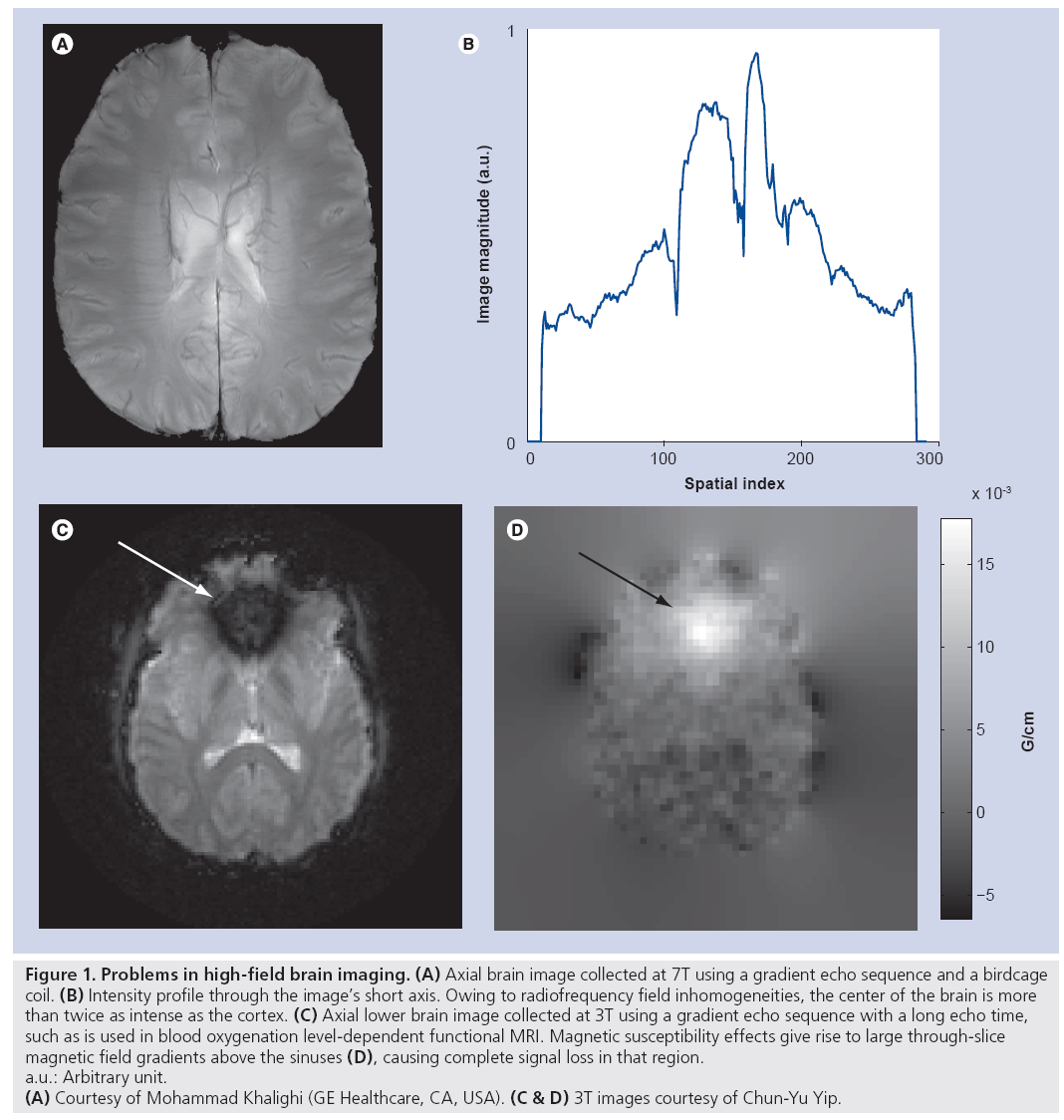
MRI at field strengths of 7 Tesla (T) and higher promises to enhance clinical diagnosis and enable new medical discoveries via benefits such as higher signal-to-noise ratio [1], increased sensitivity and spatial resolution in functional neuroimaging, increased spectral resolution in spectroscopic imaging [2], and enhanced magnetic susceptibility contrast [3]. However, just as the benefits grow with field strength, so do the technical challenges. Increased traveling wave behavior at high field gives rise to inhomogeneous transmit radiofrequency (RF) (B1+) fields and, subsequently, inhomogeneous excitation angle (or tip angle) patterns, resulting in spatially varying image contrast and even complete loss of signal [4–6]. Figure 1A illustrates this with a typical gradient echo axial brain image collected at 7T. Despite hand-tuning of the RF coil used for transmission and reception, owing to B1+ inhomogeneity, a bright signal peak appears in the center of the brain that is twice as intense as the cortex (profile plotted in Figure 1B). The large difference in signal intensity reflects the large variations in excitation flip angles across the brain that substantially degrade the diagnostic value of such an image. Figure 1C & D illustrate another substantial problem at high field strengths, that of main field B0 inhomogeneities that cause signal loss near regions of high susceptibility differences. While susceptibility- weighted imaging and blood oxygenation level-dependent functional MRI benefit from enhanced magnetic susceptibility contrast at high field strengths, the same effect also prevents their use in lower brain regions where the susceptibility differences between air in the nasal cavity and sinuses and adjacent tissues result in signal loss near the air–tissue boundaries [7]. Figure 1C shows an image acquired with a blood oxygenation level-dependent functional MRI sequence. In that image, a large through-slice B0 gradient above the nasal cavity (Figure 1D) creates through-slice phase dispersion and subsequent signal loss that renders the image unusable for functional MRI studies involving this area of the brain. Another significant challenge at high field is the safety risk posed by increased specific absorption rate (SAR), which is a measure of RF heating of biological tissue. SAR increases with RF imaging frequency, and thus increases with field strength. The US FDA places limits on the maximum local and global SAR that can be deposited into a patient. This currently limits or prevents many high-field imaging applications.
Figure 1: Problems in high-field brain imaging. (A) Axial brain image collected at 7T using a gradient echo sequence and a birdcage
coil. (B) Intensity profile through the image’s short axis. Owing to radiofrequency field inhomogeneities, the center of the brain is more
than twice as intense as the cortex. (C) Axial lower brain image collected at 3T using a gradient echo sequence with a long echo time,
such as is used in blood oxygenation level-dependent functional MRI. Magnetic susceptibility effects give rise to large through-slice
magnetic field gradients above the sinuses (D), causing complete signal loss in that region.
a.u.: Arbitrary unit.
(A) Courtesy of Mohammad Khalighi (GE Healthcare, CA, USA). (C & D) 3T images courtesy of Chun-Yu Yip.
The actual excitation angle produced by an RF pulse at a given spatial location is proportional to both the B1+ field and the nominal excitation angle (which is determined by the RF pulse) at that location. Conventional 1D excitation pulses produce uniform nominal excitation angle patterns, and therefore fail to produce uniform contrast when excited using a nonuniform B1+ field. While novel RF coil designs can mitigate B1+ inhomogeneities to a degree [8,9], no current coil design is capable of fully compensating this effect. This is partly due to the fact that at high field the shape of the B1+ field produced by a given RF coil can vary significantly between subjects. Thus, in order to achieve homogeneous excitation angles at high field, more degrees of freedom are needed to tailor a nominal excitation angle pattern to each subject that cancels the inhomogeneous pattern caused by B1+ nonuniformity. If the B1+ field is measured in a given subject, then it is possible to design RF excitation pulses that excite compensatory nominal excitation angle patterns. Because the B1+ fields vary in multiple dimensions, the pulses must produce compensatory patterns that also vary in multiple dimensions, leading to tailored multidimensional RF pulses [10,11]. In a similar fashion, the throughslice signal loss problem can be effectively mitigated using tailored multidimensional RF pulses that are designed, using measured B0 maps [12,13], to excite a pattern that cancels the phase dispersion created by through-slice B0 gradients.
However, because multidimensional tailored RF pulses have historically used gradient fields to excite one spatial frequency component at a time, they have required excessively long durations that severely hamper their efficacy. For example, the long durations of tailored multidimensional pulses for B1+ homogenization make them sensitive to B0 inhomogeneities and unsuitable for many applications requiring a uniform excitation angle distribution across a wide range of resonance frequencies. Similarly, the long durations of pulses for through-slice signal loss compensation prevent them from mitigating signal loss in multiple regions simultaneously [13]. Recently, parallel excitation using an array of localized RF coils driven by unique RF waveforms has been proposed independently by Katscher et al. [14] and by Zhu [15] as a means of reducing the duration of, or accelerating, such RF pulses. While conventional excitation assumes an RF coil producing a uniform B1+ field and deviations from this assumption are detrimental to image quality, the nonuniformity of localized coils is actually exploited in parallel excitation as a spatial encoding mechanism that permits excitation of a range of spatial frequency components simultaneously, and can be traded for gradient encoding to accelerate multidimensional excitation pulses. Parallel excitation is an exciting technology that promises to address several problems in high-field MRI.
This article will introduce parallel excitation from an applications perspective, with a focus on its application to accelerating patient-tailored RF pulses for high-field imaging. The next section will discuss the hardware required to implement parallel excitation, and provide an intuitive understanding of how parallel excitation enables RF pulse acceleration. Then the applications of parallel excitation currently under investigation will be discussed, followed by an overview of open research problems.
Multichannel parallel excitation
Hardware
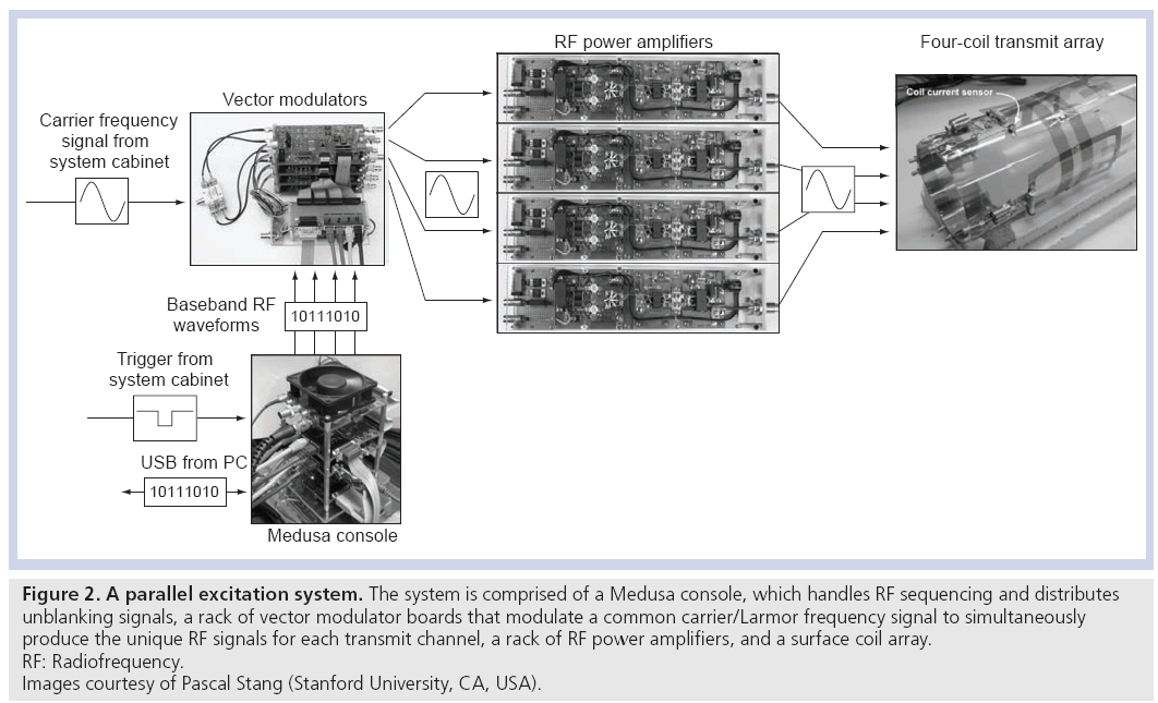
Accelerating tailored RF pulses using parallel excitation requires the ability to deliver unique RF waveforms through a multiple-channel RF coil array simultaneously. Thus, a parallel excitation system must fully replicate the components of a single-channel excitation chain to multiple channels. Figure 2 shows an example of a parallel excitation system, which is comprised of four hardware components: a Medusa spectrometer console [16], a rack of vector modulator boards (one per transmit channel), a rack of RF power amplifiers (one per transmit channel), and a transmit coil array [17,18]. The Medusa console functions as a control and logic distribution center. Prior to imaging, the digital RF pulse waveforms for each transmit channel are downloaded from a PC to the console via a USB connection. At the beginning of a repetition time (TR) period, the console receives a signal from the MRI system cabinet, which triggers it to produce digital RF pulse waveforms and send them to the vector modulator boards, where they are converted to analog signals and are applied to modulate a duplicated carrier/Larmor RF frequency signal from the system cabinet. Using a duplicated RF carrier frequency signal ensures that all channels will be in phase at the beginning of each excitation, which is a subtle but critical feature of a parallel excitation system, and is one of the major engineering difficulties encountered in modifying conventional MRI hardware to perform parallel excitation. The modulated RF signals are sent to the RF power amplifiers, and the amplified signals are sent to the coil array. In this system, the transmit coil array is composed of surface coils with no attempt made to decouple the coils in hardware, although the system is capable of digital coil decoupling using feedback from current sensors placed on the coils [19,20]. Other transmit coil array designs have been proposed that decouple the transmit elements in hardware which simplifies B1+ mapping and may reduce subject-dependence of the B1+ fields and improve power efficiency [21–24]. It is worth noting that owing to the additional hardware required for parallel excitation, the cost of a parallel excitation-enabled MRI system will likely increase compared with a standard single-channel system.
Figure 2: A parallel excitation system. The system is comprised of a Medusa console, which handles RF sequencing and distributes
unblanking signals, a rack of vector modulator boards that modulate a common carrier/Larmor frequency signal to simultaneously
produce the unique RF signals for each transmit channel, a rack of RF power amplifiers, and a surface coil array.
RF: Radiofrequency.
Images courtesy of Pascal Stang (Stanford University, CA, USA).
Accelerating tailored RF pulses
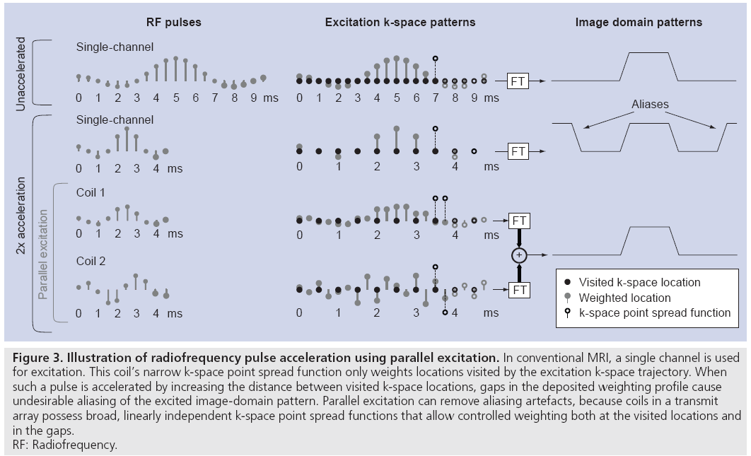
Parallel excitation is a spatial encoding mechanism that complements conventional gradient encoding. Unlike gradient encoding, however, parallel excitation encoding occurs simultaneously across a range of spatial frequencies, allowing one to trade gradient encoding for parallel excitation encoding to reduce the duration of multidimensional excitation pulses. Figure 3 illustrates this concept through a simplified 1D example of a small-tip-angle excitation. When an RF pulse excites small-tip angles, the spatial tip angle pattern is approximately the Fourier transform of the pulse, evaluated along an excitation k-space trajectory defined by the gradient waveforms [25]. The top row of Figure 3 illustrates an unaccelerated single-channel excitation. As the pulse is played out, the gradients move the coil’s k-space point spread function (equal to the Fourier transform of its B1+ map) along the excitation k-space trajectory, and the point spread function weights each visited k-space location. In Figure 3, the filled-in circles denote weighted locations as the k-space point spread function moves from left to right, while the empty circles denote locations where weighting has yet to occur. In this example, the unaccelerated RF pulse creates a sinc-shaped weighting of excitation k-space, corresponding to a rectangular profile in the image domain.
Figure 3: Illustration of radiofrequency pulse acceleration using parallel excitation. In conventional MRI, a single channel is used
for excitation. This coil’s narrow k-space point spread function only weights locations visited by the excitation k-space trajectory. When
such a pulse is accelerated by increasing the distance between visited k-space locations, gaps in the deposited weighting profile cause
undesirable aliasing of the excited image-domain pattern. Parallel excitation can remove aliasing artefacts, because coils in a transmit
array possess broad, linearly independent k-space point spread functions that allow controlled weighting both at the visited locations and
in the gaps.
RF: Radiofrequency.
The duration of an RF pulse can be reduced by decimating the set of locations visited by the excitation k-space trajectory. In multidimensional parallel excitation, the decimation increases the gaps between visited locations in excitation k-space. As is shown in the second row of Figure 3, while decimating the visited locations reduces the pulse duration, a single coil acting in isolation cannot weight the unvisited locations, resulting in undesirable aliasing of the nominal excitation pattern in the image domain. However, it is possible to create the target weighting pattern using multiple coils possessing k-space point spread functions that are broad in the decimated dimension, and will therefore simultaneously weight a neighborhood of locations around each visited location. Given a priori knowledge of the coils’ unique, linearly independent k-space point spread functions, one can design a set of pulses to create an arbitrary excitation k-space weighting. This is illustrated in the last two rows of Figure 3. When excited simultaneously, the excitation k-space weighting generated by the two coils sum, resulting in an alias-free image domain pattern excited with half the pulse duration of the single-channel excitation.
In summary, parallel excitation complements gradient encoding by enabling the controlled weighting of a full set of excitation k-space locations, including locations not visited by the excitation k-space trajectory. Since parallel excitation encoding simultaneously weights a swath of spatial frequencies, gradient encoding can be traded for parallel excitation encoding to reduce the duration of a multidimensional pulse. Given perfect linear independence between the coils’ point spread functions, one can reduce pulse duration by a factor equal to the number of coils. Perfect linear independence is impossible in practice, and pulses are typically accelerated by a smaller factor such as by half the number of transmit coils.
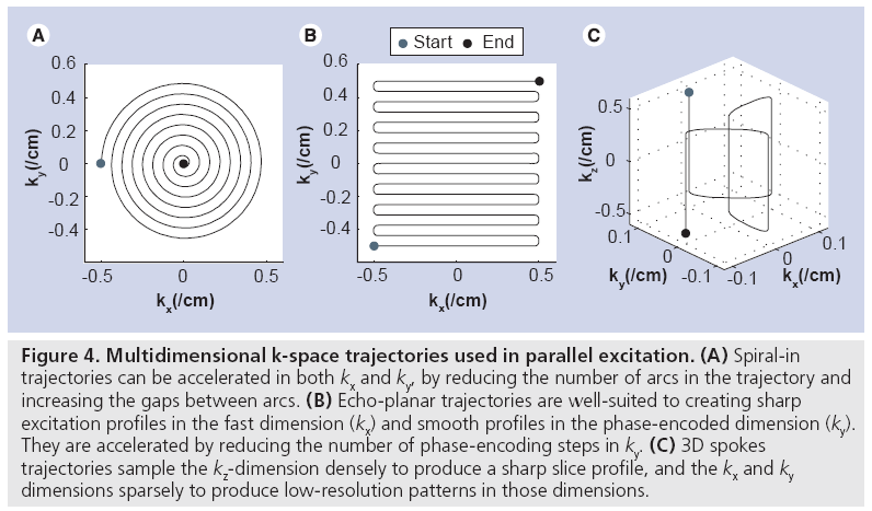
Figure 4 shows three multidimensional excitation k-space trajectories that have been used in parallel excitation. The spiral-in trajectory shown in Figure 4A is the most commonly used trajectory for 2D pulses, owing mainly to its relatively short duration (usually between 2 and 10 ms) and its ability to fully exploit the 2D acceleration afforded by cylindrical transmit arrays. A spiral pulse is accelerated by reducing the number of arcs in the trajectory and increasing the gaps between arcs. The echo-planar trajectory in Figure 4B is useful when a sharp profile is desired in the fast dimension (kx), and a smooth profile is acceptable in the phase-encoded dimension (ky). It is well-suited to linear arrays in which the coils are laid out along the phase-encoded dimension, so that the pulse can be accelerated by reducing the number of phase encoding steps in ky. The 1D example of RF pulse acceleration in Figure 3 corresponds to the phase-encoded dimension of an echo-planar pulse. Echo-planar trajectories used in excitation are generally longer in duration than spirals, usually between 8 and 20 ms. Illustrated in Figure 4C, 3D spokes trajectories sample the kz-dimension densely, and the kx and ky dimensions sparsely. Their duration is controlled by limiting the number of phase encoding locations visited in the kx – ky plane, and are well suited for B1+ and B0 shimming applications in which a sharp slice profile is desired in z, but the transmit array can perform most of the spatial encoding in x and y. Spokes trajectories are also referred to as fast-kz trajectories, echovolumar trajectories, and rungs trajectories, and are usually between 3 and 15 ms in duration.
Figure 4: Multidimensional k-space trajectories used in parallel excitation. (A) Spiral-in trajectories can be accelerated in both kx and ky, by reducing the number of arcs in the trajectory and increasing the gaps between arcs. (B) Echo-planar trajectories are well-suited to creating sharp excitation profiles in the fast dimension (kx) and smooth profiles in the phase-encoded dimension (ky). They are accelerated by reducing the number of phase-encoding steps in ky. (C) 3D spokes trajectories sample the kz-dimension densely to produce a sharp slice profile, and the kx and ky dimensions sparsely to produce low-resolution patterns in those dimensions.
Tailored parallel excitation applications
Transmit RF field (B1+) shimming
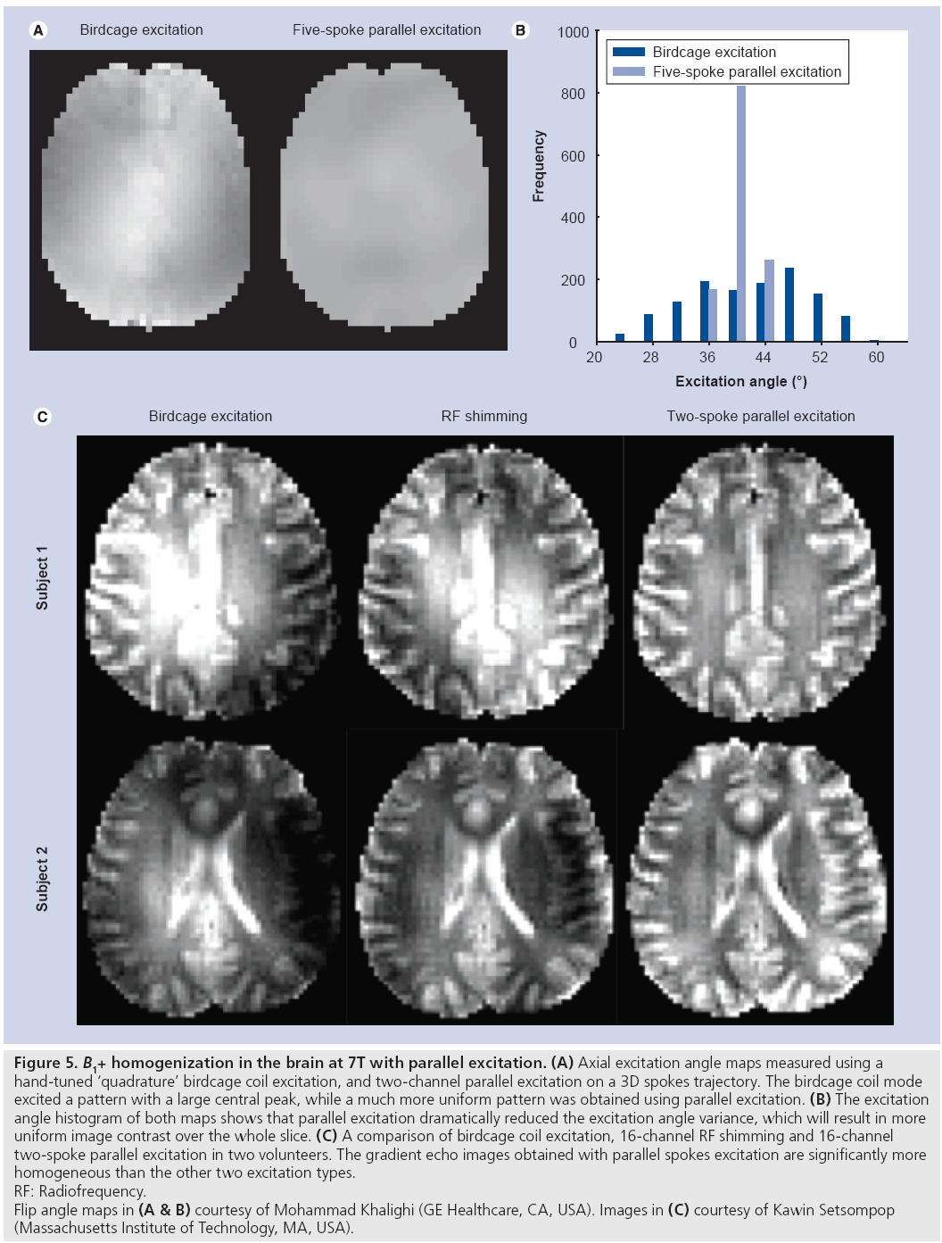
The goal of B1+ shimming using tailored parallel excitation is to excite a homogeneous flip angle pattern throughout a target slice (or slab, in 3D imaging). 3D spokes excitation k-space trajectories (Figure 4C) are well suited to this application, because they achieve high resolution in the slice dimension where a thin slice profile is desired, and low resolution in the in-plane dimension, where the target pattern varies slowly and the limited spatial encoding achieved by the trajectory is complemented by the transmit array. Spokes pulses for B1+ shimming were first proposed for application in the brain at 3T using single channel transmit [10], where it was shown that a very effective B1+ shim can be achieved by exciting an inverse Gaussian pattern in the slice plane that approximately cancels the center brightening effect, resulting in a reported 66% reduction in image nonuniformity. Parallel spokes excitation was first demonstrated at 3T by Setsompop et al. [26]. Figure 5 demonstrates the improved flip angle homogeneity achieved by parallel spokes pulses at 7T. Figure 5A & B compare in vivo flip angle maps produced by a birdcage coil driven in approximate quadrature mode against five-spoke pulses (6 ms duration) driven independently on the in-phase and quadrature channels of the same coil on a GE 7T scanner. The five-spoke pulses produce smoother excitation angle maps with a significantly narrower distribution than the quadrature excitation. Figure 5C compares in vivo images collected on a Siemens 7T scanner using a birdcage excitation, 16-channel RF shimming (equivalent to one-spoke parallel excitation) and 16-channel parallel two-spoke pulses (2.29 ms duration) [27]. Reduction in image intensity variations and more uniform contrast is easily appreciated for the two-spoke parallel excitation pulses; measured excitation angle maps reflected more than a 50% decrease in the spoke pulses’ excitation angle standard deviation, compared with birdcage excitation.
Figure 5: B1+ homogenization in the brain at 7T with parallel excitation. (A) Axial excitation angle maps measured using a
hand-tuned ‘quadrature’ birdcage coil excitation, and two-channel parallel excitation on a 3D spokes trajectory. The birdcage coil mode
excited a pattern with a large central peak, while a much more uniform pattern was obtained using parallel excitation. (B) The excitation
angle histogram of both maps shows that parallel excitation dramatically reduced the excitation angle variance, which will result in more
uniform image contrast over the whole slice. (C) A comparison of birdcage coil excitation, 16-channel RF shimming and 16-channel
two-spoke parallel excitation in two volunteers. The gradient echo images obtained with parallel spokes excitation are significantly more
homogeneous than the other two excitation types.
RF: Radiofrequency.
Flip angle maps in (A & B) courtesy of Mohammad Khalighi (GE Healthcare, CA, USA). Images in (C) courtesy of Kawin Setsompop
(Massachusetts Institute of Technology, MA, USA).
Spokes pulses are typically designed by assuming that the B1+ field is constant through the excited slice, which allows them to be designed efficiently in a separable manner. First, a sliceselective subpulse (e.g., a sinc or Shinnar–Le Roux pulse [28]) is designed. Then the weights for each kx – ky location for each coil are designed using a standard parallel excitation pulse design method [29], and are applied to the subpulses. Because the spokes trajectory only visits a small number of kx – ky locations near zero frequency, the size of the numerical problem to determine the weights is rather small, so the pulses can be designed very quickly compared with other types of parallel excitation pulses.
Because spokes pulses are comprised of a train of slice-selective subpulses similar to spectralspatial pulses [30], they tend to be spectrally selective, which can result in significant excitation angle inhomogeneity at off-resonant frequencies, even if a map of B0 inhomogeneities is included in the pulse design. For example, in practice this would be particularly problematic for non-fatsuppressed sequences, since the resulting images would contain spatially varying fat/water contrast. However, the effect can be mitigated by explicitly designing the spokes pulses to produce homogeneous excitation angle patterns across a range of frequencies, at the expense of increased inhomogeneity on resonance. Kerr et al. introduced dual-band water–fat excitation pulses, and showed that spokes pulses designed simultaneously for both water and fat frequencies are still highly effective in mitigating excitation angle inhomogeneity in the pelvis at 3T [31]. Conversely, Malik et al. proposed a method using parallel excitation to improve the performance of water-selective spectral-spatial pulses in inhomogeneous B0 fields, for fat suppression [32]. Setsompop et al. have also demonstrated spokes pulses designed to produce uniform excitation angle patterns across a 2 ppm chemical shift range, for use in chemical shift imaging [33].
It should be noted that methods for B1+ shimming using one-spoke parallel excitation have come to be known collectively as RF shimming [8,34–38]. In these methods the same RF pulse shape is used for each transmit channel, but the phase and amplitude of each channel’s pulse is adjusted to optimize B1+ homogeneity and in some instances SAR [38]. While RF shimming does not exploit the temporal degrees of freedom available in fully channel-independent parallel excitation, it greatly simplifies the pulse design, hardware, and SAR prediction for parallel excitation. Given a sufficient number of transmit coils, RF shimming has been demonstrated to deliver good B1+ homogeneity at high field, particularly in the brain.
Through-slice signal loss compensation
The goal of RF-based approaches to throughslice signal loss compensation is to excite a through-slice phase pattern equal to the negative of the phase accrued between excitation and signal collection. Because the excited phase pattern cancels the accrued phase pattern, all spins in the slice dimension are in phase when the signal is measured, so they add constructively and no signal is lost.
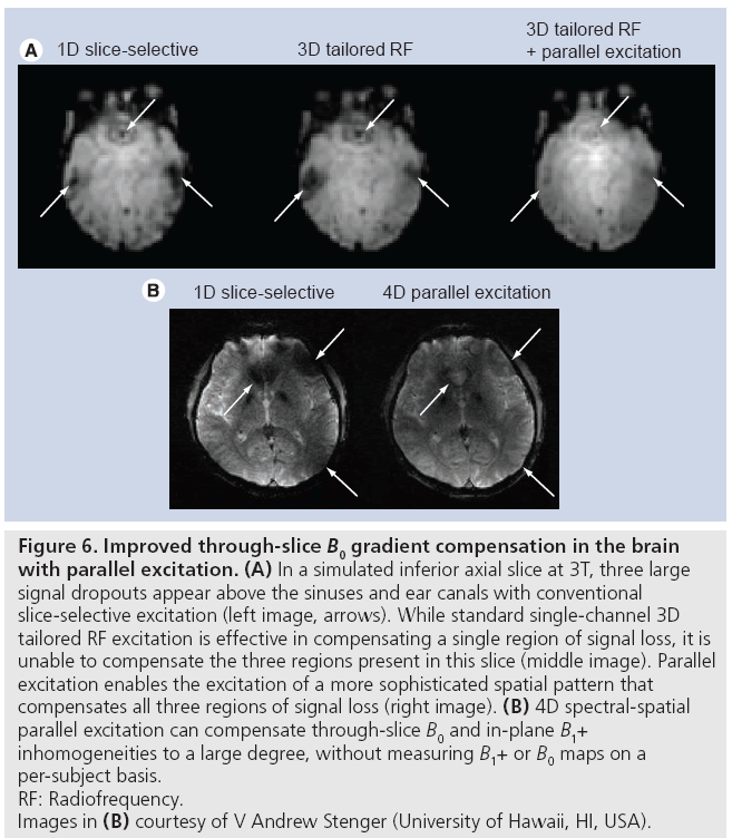
Two classes of RF-based approaches have been proposed. In one, maps of B0 inhomogeneities are measured on multiple, thinner slices within the target slice for compensation, and these maps are used to design a 3D pulse (e.g., using a spokes k-space trajectory) that excites the target negative phase pattern [12,13]. The extension of this technique to parallel excitation is straightforward, and requires the additional measurement of B1+ maps. Figure 6A illustrates the improvement in performance that parallel excitation brings to this method. In that simulated example, eightchannel parallel excitation was used to increase the in-plane spatial resolution of the pulse by a factor of three, while reducing the pulse duration by 20%. This enabled the simultaneous compensation of the three large regions of signal loss that plague inferior brain slices, whereas single-channel excitation is generally capable of compensating only one.
Figure 6: Improved through-slice B0 gradient compensation in the brain
with parallel excitation. (A) In a simulated inferior axial slice at 3T, three large
signal dropouts appear above the sinuses and ear canals with conventional
slice-selective excitation (left image, arrows). While standard single-channel 3D
tailored RF excitation is effective in compensating a single region of signal loss, it is
unable to compensate the three regions present in this slice (middle image). Parallel
excitation enables the excitation of a more sophisticated spatial pattern that
compensates all three regions of signal loss (right image). (B) 4D spectral-spatial
parallel excitation can compensate through-slice B0 and in-plane B1+
inhomogeneities to a large degree, without measuring B1+ or B0 maps on a
per-subject basis.
RF: Radiofrequency.
Images in (B) courtesy of V Andrew Stenger (University of Hawaii, HI, USA).
However, the first approach’s B0 inhomogeneity mapping requirement, as well as the required patient-specific pulse design, motivated a second RF-based approach that does not have these requirements. The second approach makes use of the observation that the magnitude of the through-slice gradient is approximately proportional to the mean B0 (or equivalently frequency) offset in the slice, with a constant of proportionality that is largely subject- and slice location-invariant [39]. Based on this relationship a 2D negative phase target excitation pattern is defined in the frequency and slice dimensions, and a spectral-spatial RF pulse [30] is designed to excite the pattern. Recently, a technique has been proposed that combines this method and B1+ homogenization using parallel excitation, to form a 4D spectral-spatial excitation that simultaneously compensates through-slice signal loss and B1+ inhomogeneities [40]. In that method, a short spokes subpulse designed to produce uniform flip angles across the slice is repeated with weightings designed to achieve the same target negative phase pattern as in the single channel method. In a multisubject evaluation of the method at 3T, the authors reported an average 90% signal recovery above the sinuses and a 20% reduction in image inhomogeneity. Figure 6B shows a representative result from that study; recovery of signal above the sinuses, as well as image intensity homogenization in multiple locations is apparent. In this particular example, B1+ maps were measured on a phantom and the pulse was designed prior to scanning the human subject. The promising results obtained in spite of potential B1+ miscalibration demonstrate that the method may be effective without collecting B1+ maps for each subject.
Restricted field-of-view imaging & spectroscopic localization
The goal of restricted (or reduced) field-of-view (rFOV) imaging is to produce an unaliased image of a volume of spins that is shrunk in one or more of the dimensions resolved by the imaging readout, so that shorter readouts can be used along the restricted dimensions [41]. Such techniques have been proposed for dynamic imaging scenarios such as cardiac [42], interventional and functional MRI [43], as well as diffusion MRI [44], where they can improve frame rates, increase achievable image resolution and reduce artifacts caused by motion and field inhomogeneities. Spectroscopic localization is a related problem, in which the goal is to restrict the spatial volume of spins to a single voxel, so that only the spectral dimension need be resolved by the signal readout [45].
Radiofrequency excitation can be used to restrict an imaging FOV in two ways: either the spin signals outside the desired imaging volume can be suppressed through consecutive RF excitation and gradient dephasing (a technique known as saturation), followed by a standard excitation pulse and an rFOV readout, or a multidimensional excitation scheme can be used to excite only spins within the reduced imaging FOV in the first place, followed directly by an rFOV readout. Owing to the long pulse durations required for multidimensional excitation-based rFOV imaging, as well as their susceptibility to B0 inhomogeneities and gradient system imperfections [46], saturation techniques have historically been favored for rFOV imaging. However, saturation can degrade imaging frame rates, particularly when a saturation module (comprised of a single RF and gradient dephaser pair) must be repeatedly applied in multiple dimensions, or when B1+ inhomogeneities require the repeated application of saturation modules to achieve acceptable signal suppression. Furthermore, since no excitation pulse of finite duration can excite exactly zero excitation angles outside of a target saturation region, saturation techniques partially suppress the signal within the rFOV. They also preclude the interleaved imaging of multiple adjacent restricted volumes, since the signals in one volume are suppressed by the saturation pulses for the other.
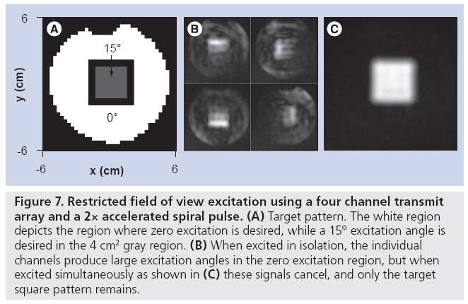
The performance of multidimensional excitation- based rFOV techniques can be substantially improved by combining them with parallel excitation to reduce pulse duration, and with gradient measurement techniques to eliminate errors caused by gradient imperfections. Ullmann et al. first demonstrated rFOV imaging with spiral parallel excitation in a biological sample in a 4.7 T animal scanner [47], where it was shown that an accurate excitation with reduced sensitivity to B0 inhomogeneity and no visible aliasing in rFOV images could be achieved on a three channel transmit array with acceleration factor of two (leading to a pulse duration of 3.5 ms). It was later demonstrated by that group and others that designing rFOV parallel RF pulses on measured excitation gradient waveforms further improves excitation accuracy [48,49]. While gradient waveform measurement using conventional imaging-based techniques can be time consuming, recent advances in NMR probe-based gradient measurement may result in insignificant measurement times, compared with other pre-scan procedures currently performed [50]. Figure 7 illustrates an application of parallel excitation to rFOV excitation. In this example, a 2× accelerated spiral pulse (excitation field of view 6 cm, 3.25 ms duration) was designed for a fourchannel transmit array (the parallel excitation hardware described in the ‘Hardware’ section), to excite a 4 × 4 cm square region of flip angle 15° (Figure 7A). Prior to pulse design, the excitation gradient waveforms were measured using the Duyn method [51], and pulses were designed on the measured trajectory. The pulse design algorithm permitted the specification of flip angle error levels inside and outside the square, which were specified to be four-times lower outside, minimizing the amount of signal that would be aliased into the square region in an rFOV acquisition [52]. Figure 7B & C show that while the individual coils excite patterns with significant flip angles outside the square, when transmitted simultaneously the out-of-square signals cancel, and only the target square remains.
Figure 7: Restricted field of view excitation using a four channel transmit array and a 2× accelerated spiral pulse. (A) Target pattern. The white region depicts the region where zero excitation is desired, while a 15° excitation angle is desired in the 4 cm2 gray region. (B) When excited in isolation, the individual channels produce large excitation angles in the zero excitation region, but when excited simultaneously as shown in (C) these signals cancel, and only the target square pattern remains.
To date, the majority of research in rFOV imaging with parallel excitation has focused on 2D excitation pulses. However, unless a 2D parallel rFOV pulse performs slice selection in one of its dimensions, imaging the magnetization it excites requires either a 3D imaging readout, a slice-selective spin echo pulse, or some form of out-of-slice saturation to restrict signal to the slice for which the rFOV pulse was designed. All these approaches severely restrict multislice or multivolume imaging, since magnetization outside the target slice is saturated by the rFOV pulse. Recently, Schneider et al. have demonstrated a novel class of 3D excitation pulses capable of restricting the excited volume in three spatial dimensions [53]. The pulses use a ‘shells’ trajectory comprised of concentric spheres, that was demonstrated to be capable of encoding a 6.4 cm field of view with 4 mm resolution in three dimensions in 5 ms. Combined with an eight-channel transmit array and a fast head gradient system, these pulses could provide excellent spectroscopic localization in the human brain.
In summary, the performance enhancements afforded by parallel excitation with measured gradients make multidimensional excitation techniques an attractive choice for rFOV imaging, and may lead to more widespread use of rFOV methods. Continuing research in this area focuses largely on the need for methods to design large-tip-angle multidimensional pulses that are required to generate spin echoes [54–57], and on the need for novel excitation gradient trajectories that simultaneously provide high spatial selectivity, low sensitivity to off-resonance and wide spectral bandwidths.
Emerging applications
Transmit array encoding
Prior to the emergence of parallel excitation, image signal encoding using RF excitation had been proposed to alleviate some of the drawbacks to gradient encoding, including peripheral nerve stimulation, eddy current effects and acoustic noise. RF encoding could be performed by constructing coils with a linear B1+ variation through an object, and incrementing hard pulse excitations to induce sinusoidal signal magnitude modulations that can be converted to phase modulation using a 90° pulse [58], or via specialized RF transmit arrays capable of exciting magnetization with linear spatial phase patterns [59], or via pulses that spatially encode signal in a non-Fourier domain, such as a wavelet domain [60]. However, owing to several issues including limits in achievable spatial resolution, high SAR and long imaging times required to minimize artifacts due to irregular T1 relaxation when encoding pulses excite different flip angle patterns in each acquisition period, these methods have not emerged into common use (although the method in [59] does not suffer some of these drawbacks and is currently under heavy development). However, the additional degrees of freedom provided by parallel transmit arrays has created renewed interest in this area, and various methods for RF signal encoding using parallel excitation have been proposed.
One class of proposed parallel RF encoding methods uses different linear combinations of RF coils to create spatially varying phase patterns that either replace gradient encoding [61] or complement it [62]. Implementation of these approaches amounts to measuring B1+ maps, determining a set of RF shims (i.e., one-spoke B1+ shimming pulses) with different spatial phase patterns, acquiring image data with each RF shim, and reconstructing the images given knowledge of the phase patterns. Katscher et al. showed that it is possible to use a parallel transmit array in this way to acquire low-resolution images with no gradient encoding [61]; it may be possible to increase resolution using denser coil arrays with more channels. Furthermore, they showed that it was possible to synthesize a large set of usable phase encoding functions while constraining the maximum excitation angle deviation in each function. The ability to create such an encoding set is important if such excitations are to be used in fast or T1-weighted imaging sequences where irregular T1 relaxation due to large flip angle deviations will result in image artifacts. Usman et al. [62] have proposed the use of similar phase encoding RF shims to complement gradient encoding in compressed sensing acquisitions [63]. In that scheme, RF encoding is used to create small random shifts in k-space in concert with uniformly incremented gradient phase encoding steps, avoiding eddy current artifacts that accompany nonuniformly incremented gradient phase encoding. However, it may not be necessary to restrict the set of excited phase patterns to linear functions; RF encoding can also be used to excite nonlinear phase patterns that may further enhance compressed sensing performance [62]. Currently, however, the degree of excitation angle uniformity between subsequent excitations required to produce acceptable image quality in practice is not known, and rather large variations may be acceptable. If this is the case then another, simpler type of RF encoding method may be feasible, that aims not to replace gradient encoding but to reduce the impact of B1+ inhomogeneity, without requiring B1+ mapping or multidimensional excitation [64]. In this method, multiple undersampled datasets are acquired in an interleaved fashion using different coil array modes for excitation, which are equivalent to one-spoke parallel excitation pulses with uniform magnitudes and different phase increments between adjacent coils. Because it can be expected that different coil modes will have signal dropouts in different locations, a combination of the images produced by multiple modes is likely to be more homogeneous than any single mode’s image. Undersampling the acquisition avoids the temporal penalty of acquiring an image for each mode, and a combined image can be reconstructed using the GRAPPA parallel imaging technique [65], where the modes are effectively treated as elements in a receive coil array. Experimental demonstrations of the method showed that brain and abdominal images could be acquired at 7T with no signal dropouts [64].
Eliminating induced currents in embedded wires
Embedded metal wires such as guidewires, cardiac pacemaker leads and deep brain stimulator leads pose a significant safety hazard in the MRI environment. This is because the transmitting RF field can couple to these wires, inducing currents that cause burns. While many MR-safe designs of such wires have been proposed, in general the ability to safely scan around arbitrary wires is desirable. Recently, an approach to safe MRI in the presence of long conducting wires using parallel excitation has been proposed [66,67]. The idea is to exploit the additional degrees of freedom provided by a transmit array to produce a B1+ field that at the same time is usable for imaging, and does not couple significant current to a given wire. The wire would be effectively treated as an element of the transmit array, and the goal would be to decouple it from the other elements of the array. Initial investigations showed that measurements from a current sensor placed on the wire can be used to distinguish coil array modes that couple to the wire from modes that do not (and can therefore be safely used for excitation). B1+ mapping was used as validation of the approach, since current coupled to a wire appears as a sharp disturbance in otherwise smooth B1+ maps. Indeed, in imaging slices coinciding with the current sensor measurements, B1+ maps of the coupling modes contained a wire artifact, while maps of the noncoupling modes contained no visible artifact. While it may be feasible in practice to place current sensors on guidewires used in image-guided interventions, this approach is not feasible for measuring currents induced in wires that reside entirely in the body, such as pacemaker and stimulator leads. For fully embedded wires, it has been shown that B1+ mapping can be used in place of current sensor measurements. Finally, it has also been demonstrated that because a guidewire will still couple to the receive coil, this technique does not diminish the visibility of a guidewire, which is desirable to the interventionalist. While the impact of this work may be largest at low field strengths for image-guided interventions, it may also enable safe cardiac and neuroimaging in people with pacemakers and brain stimulators at high field strengths.
Nonlinear gradients & parallel excitation
Conventional MRI uses linear gradient fields for spatial encoding that create a linear mapping of location to signal frequency, so that a Fourier transform of the received signal unambiguously resolves the spatial signal distribution. Linear fields convey several advantages, including constant resolution across an object, simple image reconstruction, and isotropic parameter (e.g., diffusion) encoding. However, the large magnetic fields created by linear gradient coils outside their linear region can be quite large; as a consequence, concerns over peripheral nerve stimulation are currently a limiting factor in improving gradient performance. As an alternative, nonbijective gradient encoding has been proposed in which nonlinear gradient fields that do not provide an unambiguous spatial mapping are used in concert with parallel imaging to resolve spatial ambiguities [68]. Since the peak gradient field magnitude of nonbijective gradients can be located much closer to the object, for a given maximum spatial resolution nonbijective gradients present significantly less risk of peripheral nerve stimulation, permitting faster gradient switching and shorter signal readouts.
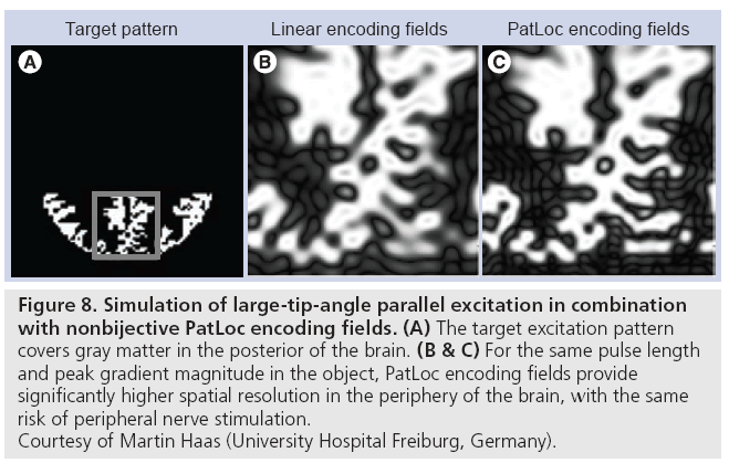
Recently, the combination of parallel excitation and nonbijective gradients has also been proposed [69], where nonbijective gradients permit either the excitation of higher resolution patterns near the object’s periphery for a fixed pulse length, or shorter pulse lengths for a given maximum spatial resolution. Just as parallel imaging is required to resolve spatial ambiguities in image reception using nonbijective gradients [68], parallel excitation is required to suppress aliasing in excited patterns when using nonbijective gradients. Figure 8 compares the performance of parallel excitation using linear gradient fields and PatLoc nonbijective gradient fields in large-tip-angle parallel excitation [70], and shows that for the same pulse duration and peak gradient field within the object, the pattern produced with nonbijective gradients has a significantly higher spatial resolution than that produced with linear gradients.
Figure 8: Simulation of large-tip-angle parallel excitation in combination
with nonbijective PatLoc encoding fields. (A) The target excitation pattern
covers gray matter in the posterior of the brain. (B & C) For the same pulse length
and peak gradient magnitude in the object, PatLoc encoding fields provide
significantly higher spatial resolution in the periphery of the brain, with the same
risk of peripheral nerve stimulation.
Courtesy of Martin Haas (University Hospital Freiburg, Germany).
Open problems
Transmit RF field (B1+) mapping
Conventional parallel excitation requires B1+ maps to be measured for each coil in the transmit array. In the context of the parallel excitation illustration in Figure 3, the B1+ maps are the Fourier transforms of the coils’ k-space point spread functions, which must be known in order to determine how to tailor each coil’s k-space weighting, or equivalently its RF pulse. Many methods for B1+ mapping existed prior to the emergence of parallel excitation; however, parallel excitation has generated a renewed interest in the topic.
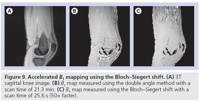
Because B1+ map measurement will become part of the prescan procedure in an acquisition using parallel transmit, recent work has focused mainly on reducing acquisition time. For example, an accelerated version of the classic ‘double angle’ method has been proposed [71,72], in which a train of adiabatic saturation pulses are played at the end of each TR that reset the signal and eliminate the double angle method’s strong sensitivity to T1, which had previously required the use of TRs of up to several seconds. Using this technique in combination with fast spiral imaging, the authors reported a scan time of 3 s per coil in one slice, or 24 s for an entire eight-channel head array, corresponding to more than an order of magnitude acceleration over the standard method. Entirely new approaches to B1+ mapping have also been developed, such as a method that exploits a phenomenon familiar to NMR researchers known as the ‘Bloch–Siegert shift’ in which an RF pulse played far offresonance induces a phase shift in on-resonant spins [73]. The method’s insensitivity to long T1s and B0 offsets make it robust and fast. A comparison of the Bloch-Siegert B1+ mapping method to the double angle method is shown in Figure 9. In this scenario, the Bloch-Siegert method was 50-times faster than the double angle method, and produced a map that did not contain the T1-induced errors that manifested as large B1+ values in the fluid around the knee in the double angle map. In addition to innovative imaging sequences to directly accelerate B1+ mapping, methods have also been developed that improve robustness for a given B1+ measurement time, thereby improving the quality of rapidly acquired B1+ maps. For example, one can synthesize a set of virtual coils with a tighter distribution of B1+ values, compared with the physical coil’s B1+ maps [74]. A tighter distribution of B1+ values reduces noise sensitivity and permits additional optimization of mapping sequences. Accelerating B1+ mapping using compressed sensing has also been proposed [75]. In that method, B1+ maps are reconstructed from undersampled data by incorporating the a priori knowledge that the B1+ maps will be spatially smooth into the reconstruction algorithm, and it was reported that an accurate map could be measured using only 40% of a fully sampled dataset.
Ultimately, the degree to which B1+ mapping can be accelerated will depend on the pulse being designed. For example, pulses with highresolution excitation k-space trajectories, such as spiral and echo-planar excitations for rFOV imaging, will require B1+ maps at a higher resolution and with lower error than low-resolution pulses using spokes trajectories. Some applications may even tolerate a moderate amount of B1+ measurement bias such as may be introduced by incomplete T1 relaxation, permitting further acceleration. While a significant research effort has been invested in accelerating B1+ mapping, some researchers have also sought to obviate it, through alternative pulse design methods that do not require B1+ maps [76], and coil designs that are insensitive to patient loading, so that B1+ maps need not be measured for each patient [23].
SAR prediction & control
The safety concern posed by increased SAR at high main field strengths, as well as the increasing complexity of predicting and managing it, is a significant roadblock to high-field MRI. Predicting local and global SAR requires knowledge of both the tissue conductivity and the electric fields accompanying each coil’s RF transmit magnetic fields in the subject. In parallel excitation, if the patient conductivity and electric fields were known a priori, limits on the peak local and global SAR could be incorporated into RF pulse design, and multidimensional parallel excitation pulses could even reduce SAR compared with conventional excitations [15,77]. For example, in a multidimensional parallel pulse design the extra degrees of freedom provided by parallel excitation could be used to minimize SAR, rather than to accelerate the pulse. To illustrate this concept, in the unaccelerated excitation of a 2D pattern such as a square, coils distant to the square could be switched off to minimize SAR, and only coils close to the square could be used for excitation. It has been shown that SAR increases approximately linearly with pulse acceleration [77,78]; roughly speaking, if the example square excitation pulse were accelerated, then coils distant to the square would be switched on and used to cancel aliased excitation created by the coils close to the square, increasing the total power deposition. SAR could also be controlled in pulse design by adjusting the rate at which the excitation k-space trajectory is traversed, using an extension of the SAR-reducing variable rate selective excitation technique to parallel excitation [79].
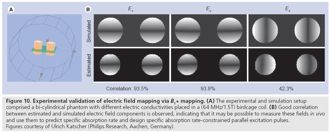
Unfortunately, while the transmit RF magnetic field can be (partially) directly measured using MRI, the accompanying electric field, conductivity and tissue density that determine SAR cannot. While at low field strengths (1.5T and below) quasi-static electric field approximations provide SAR predictions that are largely patientindependent, the shortened RF wavelength at high fields (approximately 14 cm at 7T) leads to large variations in the electric field patterns between subjects. Recently, a method for estimating electric field and conductivity maps have been proposed that uses (measurable) B1+ fields as input [80]. As is illustrated in Figure 10, by making some assumptions regarding the receive magnetic field and the z-component of the transmit RF magnetic field (which is currently not measurable using MRI), the authors demonstrated good correspondence between electric field maps measured in a phantom experiment and in a simulation of that experiment.
Figure 10: Experimental validation of electric field mapping via B1+ mapping. (A) The experimental and simulation setup comprised a bi-cylindrical phantom with different electric conductivities placed in a (64 MHz/1.5T) birdcage coil. (B) Good correlation between estimated and simulated electric field components is observed, indicating that it may be possible to measure these fields in vivo and use them to predict specific absorption rate and design specific absorption rate-constrained parallel excitation pulses. Figures courtesy of Ulrich Katscher (Philips Research, Aachen, Germany).
Pulse design
Initial demonstrations of parallel excitation focused on the acceleration of 2D small-tip excitation pulses: Katscher et al. presented an accelerated spiral excitation [14], while Zhu presented an accelerated echo-planar excitation [15]. Accompanying these two demonstrations were two different small-tip parallel pulse design algorithms: Katscher et al. introduced a k-space domain method suitable for non-Cartesian pulses, while Zhu introduced a spatial-domain method tailored to an echo-planar trajectory. Later, another spatial domain method generalized to arbitrary trajectories was introduced [29], and since then, most new small-tip pulse design algorithms have been based on this approach. However, there are many open problems in parallel excitation pulse design.
One significant challenge in parallel excitation pulse design is computational speed. Once B1+ maps are measured, parallel excitation pulses must be designed while the patient lies in the scanner. In multislice studies, prior to imaging a distinct set of pulses may need to be designed for each slice, as well as for multiple excitations (e.g., the 90° and 180° pulses in a spin echo sequence). Ideally, all pulses for a study could be designed in under a minute. Currently, however, to avoid large matrix inversions, most pulse design algorithms are iterative, and can take up to several minutes to arrive at a solution. Parallel excitation pulse design usually involves the solution of an overdetermined set of linear equations, which can be quite large, especially for 3D pulse design. A typical 2D pulse design problem has a spatial dimension in the order of several thousand locations and a few thousand design variables; a typical 3D design will have a spatial dimension in the tens of thousands and a few thousand design variables. In the small-tip angle regime, in the absence of time-dependent effects such as off-resonance and exponential signal decay, nonuniform fast Fourier transforms (NUFFTs) [81] can be used to rapidly evaluate the pattern excited by the pulse at a given iteration; time- or frequencysegmentation approaches can be used together with NUFFTs to incorporate time-dependent effects with a moderate increase in computation time [13]. Further acceleration of smalltip designs has been achieved by recasting the design problem so that the Hessian matrix is Toeplitz and can be evaluated using standard FFTs (to replace NUFFTs, which require an additional gridding operation), which accelerates iterative pulse design by a factor of two [82]. It has also been proposed to design pulses using graphics processing units to finely parallelize the matrix-vector multiplications used in iterative algorithms, and approximately one order of magnitude reduction in small-tip pulse design time has been reported using this approach [83]. In addition to parallelization, pulse design might be accelerated via preconditioning, initializing design iterations with previously designed pulses for a similar problem, varying the resolution of the spatial design grid, and parameterizing pulses (e.g., using spline functions). Unfortunately, in the large-tip-angle regime the Fourier relationship between a pulse and its excited pattern does not hold, and as a result large-tip-angle pulse design typically requires an order of magnitude or more compute time, even when accelerated via approximations that do allow the use of NUFFTs to compute search directions [54,57].
Another significant challenge is the design of large-tip-angle pulses, which is made difficult by the nonlinearity of the spin system’s response to large-tip-angle RF pulses. As a consequence, in contrast to the linear small-tip-angle case it is difficult to develop a large-tip-angle pulse design algorithm that can be relied upon to always converge to an optimal solution. While the Shinnar–Le Roux algorithm can be used to robustly design optimal 1D single-channel pulses [28], no method currently extends this ability to parallel or even general multidimensional excitation. There is one exception to this: ‘self-refocused’ pulses such as spiral pulses can be designed using small-tip design tools and scaled to produce large-tip angles without incurring significant distortion [55,84], so long as they are not highly accelerated and do not compensate time-dependent effects such as off-resonance. However, a more general design method is desirable. Some researchers have proposed the use of global optimization routines for pulse design problems of smaller dimensions, such as large-tip-angle B1+ shimming spokes pulse designs [85,86]; however, such approaches are not currently computationally feasible for designing pulses with more than a handful of parameters, such as spiral pulses. Currently, most large-tip pulse design methods are based on an extension of the optimal control pulse design algorithm [87] to parallel excitation [56]. However, the optimal control algorithm has three significant drawbacks. First, it requires two computationally expensive Bloch equation simulations at each iteration to calculate a search direction that can decrease an excitation error metric, and additional Bloch simulations to evaluate the error metric for points along the search direction. Second, owing to the computational infeasibility of calculating a Hessian to the excitation error metric, gradient descent is used for minimization, and as a result a large number of iterations are often necessary to reach an optimal point. To a large degree, these first two drawbacks are addressed by the fast optimal control method [57], which dramatically reduces the number of Bloch simulations required to reach an optimal point using a perturbation analysis that permits fast calculation of a search direction using NUFFTs. The method is related to inexact Newton methods [88], and the computed search directions reach an optimal point significantly faster than standard optimal control. The third drawback is that, in spite of their name, owing to the nonlinearity of the Bloch equation the pulses converged to by optimal control methods are not guaranteed to be globally optimal. Hence, there is currently a need for fast, general and globally optimal large-tip-angle parallel excitation pulse design algorithms.
In many of the proposed applications for parallel excitation, the imaging sequence’s trajectory will be of higher resolution than one or more dimensions of the excitation pulse’s trajectory. For example, a spokes pulse achieves high resolution in the slice-select dimension, but very low resolution in the imaging plane, and almost any imaging sequence can be expected to resolve finer details than could be excited by such a pulse. In this situation (and assuming that one need not satisfy Carr–Purcell– Meiboom–Gill conditions), the phase pattern excited by the pulse in the imaging plane is of no consequence, and can be jointly optimized with the RF, leading to more accurate or more homogeneous flip angle profiles than a constant phase profile, as has been demonstrated in spiral and spokes excitations at 7T [89]. The same situation will also frequently hold for higherresolution pulses such as spiral and echo-planar pulses. Even if the imaging trajectory is not of a higher resolution than the excitation trajectory, the target phase can be relaxed in a constrained manner so that the excited pattern does not contain higher spatial frequencies than are resolved by imaging [89]. Currently, however, algorithms for jointly optimizing RF and target phase find locally optimal solutions; the globally optimal RF and target phase solutions may be significantly more accurate than those currently found, and further investigation of this possibility is warranted.
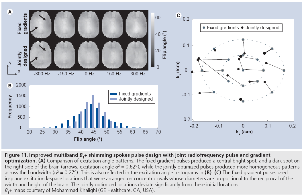
Unlike in imaging, where the distribution of energy in the k-space domain is not known prior to imaging, in excitation the target excitation pattern is usually fully specified prior to pulse design. This permits gradient waveforms to be designed that optimally sample excitation k-space given some constraint on pulse length, thereby providing the best possible tradeoff between excitation error, RF power and pulse duration. Two classes of methods for jointly designing RF and gradient waveforms have been proposed. First, a gradient descent-based method for small-tip RF and gradient design was proposed [90], in which the phase encoding locations of an echo-planar (or spokes) trajectory were optimized locally, given an initially uniform sampling pattern. This approach has also been extended to large-tip-angle pulse design [91]. These methods have the desirable ability to compensate time-dependent effects during excitation such as B0 inhomogeneities, and are compatible with designing multiband pulses (e.g., water–fat B1+-shimming spokes pulses [91]). Figure 11 illustrates an implementation of the small-tip method for multiband B1+ shimming spokes pulse design. In that example, two sets of 17-spoke pulses were designed to excite uniform flip angle patterns in the brain across a 2 ppm bandwidth for use in chemical shift imaging at 7T. In the ‘fixed gradients’ set, the in-plane excitation k-space encoding locations were fixed prior to RF design. In the ‘jointly designed’ set, the k-space locations were jointly optimized with the RF. In both sets, the target excitation phase patterns were also optimized. Figure 11 shows that the jointly designed pulse set excited significantly more homogeneous patterns across the frequency range, and that the jointly optimized sampling locations were significantly different than the initial locations. However, because the Bloch equation is nonlinear in the gradients at all tip angles, the solutions reached by gradient-based methods are locally optimal, and in many cases better solutions exist. When time-dependent effects are ignored, methods based on sparse approximation can be used to come closer to a globally optimal solution. Several similar methods have been proposed that use either greedy algorithms or sparsity-regularized least-squares algorithms to solve the sparse approximation problem [91–95]; however, these methods are not able to compensate time-dependent effects and are not multiband compatible. Thus, a method that is both globally optimal and can compensate time-dependent effects is desired, but has yet to be developed.
Figure 11: Improved multiband B1+ shimming spokes pulse design with joint radiofrequency pulse and gradient
optimization. (A) Comparison of excitation angle patterns. The fixed gradient pulses produced a central bright spot, and a dark spot on
the right side of the brain (arrows, excitation angle σ2 = 0.62°), while the jointly optimized pulses produced more homogeneous patterns
across the bandwidth (s2 = 0.27°). This is also reflected in the excitation angle histograms in (B). (C) The fixed gradient pulses used
in-plane excitation k-space locations that were arranged on concentric ovals whose diameters are proportional to the reciprocal of the
width and height of the brain. The jointly optimized locations deviate significantly from these initial locations.
B1+ maps courtesy of Mohammad Khalighi (GE Healthcare, CA, USA).
Future perspective
Parallel excitation provides new degrees of freedom to tailor RF fields to the patient that will prove indispensable to high-field MRI. While straightforward transmit field homogenization will be the first application to reach the clinic, others will soon follow as the ability to rapidly collect calibration data for multidimensional RF pulse design improves, along with the ability to predict patient heating and rapidly and robustly design multidimensional RF pulses.
Financial & competing interests disclosure
The authors are employees of GE Global Research, Munich, Germany. The authors have no other relevant affiliations or financial involvement with any organization or entity with a financial interest in or financial conflict with the subject matter or materials discussed in the manuscript apart from those disclosed.
No writing assistance was utilized in the production of this manuscript.
References
Papers of special note have been highlighted as:
• of interest
- Vaughan JT, Garwood M, Collins CM et al.: 7T vs. 4T: RF power, homogeneity, and signal-to-noise comparison in head images. Magn. Reson. Med. 46(1), 24–30 (2001).
- Hetherington HP, Pan JW, Chu WJ, Mason GF, Newcomer BR: Biological and clinical MRS at ultra-high field. NMR Biomed. 10(8), 360–371 (1997).
- Duyn JH, van Gelderen P, Li TQ, de Zwart JA, Koretsky AP, Fukunaga M: High-field MRI of brain cortical substructure based on signal phase. Proc. Natl Acad. Sci. 104(28), 11796–11801 (2007).
- Van de Moortele PF, Akgun C, Adriany G et al.: B1 destructive interferences and spatial phase patterns at 7T with a head transceiver array coil. Magn. Reson. Med. 54(6), 1503–1518 (2005).
- Kangarlu A, Baertlein BA, Lee R et al.: Dielectric resonance phenomena in ultra high field MRI. J. Comput. Assist. Tomogr. 23(6), 821–831 (1999).
- Tropp J: Image brightening in samples of high dielectric constant. J. Magn. Reson. 167(1), 12–24 (2004).
- Lipschutz B, Friston KJ, Ashburner J, Turner R, Price CJ: Assessing study-specific regional variations in fMRI signal. Neuroimage 13(2), 392–398 (2001).
- Vaughan JT, Adriany G, Snyder CJ et al.: Efficient high-frequency body coil for high-field MRI. Magn. Reson. Med. 52(4), 851–859 (2004).
- Alsop DC, Connick TJ, Mizsei G: A spiral volume coil for improved RF field homogeneity at high static magnetic field strength. Magn. Reson. Med. 40(1), 49–54 (1998).
- Saekho S, Yip CY, Noll DC, Boada FE, Stenger VA: Fast-kz three-dimensional tailored radiofrequency pulse for reduced B1 inhomogeneity. Magn. Reson. Med. 55(4), 719–724 (2006).
- Saekho S, Boada FE, Noll DC, Stenger VA: Small tip angle three-dimensional tailored radiofrequency slab-select pulse for reduced B1 inhomogeneity at 3T. Magn. Reson. Med. 53(2), 479–484 (2005).
- Stenger VA, Boada FE, Noll DC: Threedimensional tailored RF pulses for the reduction of susceptibility artifacts in T2*-weighted functional MRI. Magn. Reson. Med. 44(4), 525–531 (2000).
- Yip CY, Fessler JA, Noll DC: Advanced three-dimensional tailored RF pulse for signal recovery in T2*-weighted functional magnetic resonance imaging. Magn. Reson. Med. 56(5), 1050–1059 (2006).
- Katscher U, Börnert P, Leussler C, van den Brink JS: Transmit SENSE. Magn. Reson. Med. 49(1), 144–150 (2003).
- Y Zhu: Parallel excitation with an array of transmit coils. Magn. Reson. Med. 51(4), 775–784 (2004).
- Stang P, Conolly S, Pauly JM, Scott GC: MEDUSA: a scalable MR console for parallel imaging. Proceedings 15th Scientific Meeting, International Society for Magnetic Resonance in Medicine. Berlin, Germany, 19–25 May 2007.
- Scott G, Overall W, Pauly J, Stang P, Kerr A: A vector modulation transmit array system. Proceedings 14th Scientific Meeting, International Society for Magnetic Resonance in Medicine. Seattle, WA, USA, 6–12 May 2006.
- Stang P, Kerr AB, Pauly JM, Scott G: An extensible transmit array system using vector modulation and measurement. Proceedings 16th Scientific Meeting, International Society for Magnetic Resonance in Medicine. Toronto, Ontario, Canada, 3–9 May 2008.
- Stang PP, Kerr AB, Grissom WA, Pauly J, G Scott: Vector iterative pre-distortion: an auto-calibration method for transmit arrays. Proceedings 17th Scientific Meeting, International Society for Magnetic Resonance in Medicine. Honolulu, Hawaii, 18–24 April 2009.
- Kerr AB, Grissom WA, Stang P, Scott GC, Pauly JM: B1 mapping and parallel excitation using vector decoupling. Proceedings 17th Scientific Meeting, International Society for Magnetic Resonance in Medicine. Honolulu, Hawaii, 18–24 April 2009.
- Heilman J, Gudino N, Riffe M, Liu P, Griswold M: A four channel transmission array based on CMCD amplifier. Proceedings 17th Scientific Meeting, International Society for Magnetic Resonance in Medicine, Honolulu, Hawaii, 18–24 April 2009.
- Kurpad KN, Wright SM, Boskamp EB: RF current element design for independent control of current amplitude and phase in transmit phased arrays. Concepts Magn. Reson. Part B Magn. Reson. Eng. 29B(2), 75–83 (2006).
- Ibrahim TS, Zhao T, Jefferies E, Zheng H, Boada FE: 5 decoupled sets of coupled coils: an 8-20 channel subject-insensitive array for 7T applications. Proceedings 18th Scientific Meeting, International Society for Magnetic Resonance in Medicine. Stockholm, Sweden, 1–7 May 2010.
- Nam H, Grissom WA, Wright SM: Application of RF current sources in transmit SENSE. Proceedings 14th Scientific Meeting, International Society for Magnetic Resonance in Medicine. Seattle, WA, USA, 6–12 May 2006.
- Pauly JM, Nishimura DG, Macovski A: A k-space analysis of small-tip-angle excitation. J. Magn. Reson. 81, 43–56 (1989).
- Setsompop K, Wald LL, Alagappan V et al.: Parallel RF transmission with eight channels at 3 Tesla. Magn. Reson. Med. 56(5), 1163–1171 (2006).
- Setsompop K, Alagappan V, Gagoski B et al.: Slice-selective RF pulses for in vivo B1+ inhomogeneity mitigation at 7 Tesla using parallel RF excitation with a 16-element coil. Magn. Reson. Med. 60(6), 1422 (2008).
- Pauly JM, Le Roux P, Nishimura DG, Macovski A: Parameter relations for the Shinnar–Le Roux selective excitation pulse design algorithm. IEEE Trans. Med. Imaging 10, 53–65 (1991).
- Grissom WA, Yip CY, Zhang Z, Stenger VA, Fessler JA, Noll DC: Spatial domain method for the design of RF pulses in multicoil parallel excitation. Magn. Reson. Med. 56(3), 620–629 (2006).
- Meyer CH, Pauly JM, Macovski A, Nishimura DG: Simultaneous spatial and spectral selective excitation. Magn. Reson. Med. 15(2), 287–304 (1990).
- Kerr AB, Etezadi-Amoli M, Fautz H-P et al.: Dual-band RF shimming at high-field with parallel excitation. Proceedings 17th Scientific Meeting, International Society for Magnetic Resonance in Medicine. Honolulu, Hawaii, 18–24 April 2009.
- Malik SJ, Larkman DJ, O’Regan DP, Hajnal JV: Subject-specific water-selective imaging using parallel transmission. Magn. Reson. Med. 63(4), 988–997, 2010.
- Setsompop K, Alagappan V, Gagoski BA et al.: Broadband slab selection with B1+ mitigation at 7T via parallel spectral-spatial excitation. Magn. Reson. Med. 61, 493–500 (2009).
- Vaughan JT, Hetherington HP, Otu JO, Pan JW, Pohost GM: High frequency volume coils for clinical NMR imaging and spectroscopy. Magn. Reson. Med. 32(2), 206–218 (1994).
- Hoult DI: Sensitivity and power deposition in a high-field imaging experiment. J. Magn. Reson. Imag. 12(1), 46–67 (2000).
- Ibrahim TS, Lee R, Baertlein BA, Abduljalil AM, Zhu H, Robitaille PM: Effect of RF coil excitation on field inhomogeneity at ultra high fields: a field optimized TEM resonator. Magn. Reson. Imaging 19(10), 1339–1347 (2001).
- Mao W, Smith MB, Collins CM: Exploring the limits of RF shimming for high-field MRI of the human head. Magn. Reson. Med. 56(4), 918–922 (2006).
- van den Berg CAT, van den Bergen B, van de Kamer JB et al.: Simultaneous B1+ homogenization and specific absorption rate hotspot suppression using a magnetic resonance phased array transmit coil. Magn. Reson. Med. 57(3), 577–586 (2007).
- Yip CY, Yoon D, Olafsson VT et al.: Spectral-spatial pulse design for throughplane phase precompensatory slice selection in T2-weighted functional MRI. Magn. Reson. Med. 61(5), 1137–1147 (2009).
- Yang C, Deng W, Alagappan V, Wald LL, Stenger VA: Four-dimensional spectralspatial RF pulses for simultaneous correction of B1+ inhomogeneity and susceptibility artifacts in T2*-weighted MRI. Magn. Reson. Med. 64(1), 1–8 (2010).
- Hu X, Parrish T: Reduction of field of view for dynamic imaging. Magn. Reson. Med. 31(6), 691–694 (1994).
- Alley MT, Pauly JM, Sommer FG, Pelc NJ: Angiographic imaging with 2D RF pulses. Magn. Reson. Med. 37(2), 260–267 (1997).
- Pisani L, Bammer R, Glover G: Restricted field of view magnetic resonance imaging of a dynamic time series. Magn. Reson. Med. 57(2), 297–307 (2007).
- Saritas EU, Cunningham CH, Lee JH, Han ET, Nishimura DG: DWI of the spinal cord with reduced FOV single-shot EPI. Magn. Reson. Med. 60(2), 468–473 (2008).
- Ordidge RJ, Connelly A, Lohman JAB: Image-selected in vivo spectroscopy (ISIS): a new technique for spatially selective NMR spectroscopy. J. Magn. Reson. 66(2), 283–294 (1986).
- Oelhafen M, Pruessmann KP, Kozerke S, Boesiger P: Calibration of echo-planar 2D-selective RF excitation pulses. Magn. Reson. Med. 52(5), 1136–1145 (2004).
- Ullmann P, Schubert F, Haueisen R et al.: Flexible feature specific inner-volume selection with transmit SENSE: methods and applications in humans, animals and biological samples. Proceedings 14th Scientific Meeting, International Society for Magnetic Resonance in Medicine. Seattle, WA, USA, 6–12 May 2006.
- Ullmann P, Haas M, Hennel F et al.: Parallel excitation experiments using measured k-space trajectories for pulse calculation. Proceedings 16th Scientific Meeting, International Society for Magnetic Resonance in Medicine. Toronto, Canada, 3–9 May 2008.
- Wu X, Vaughan JT, Ugurbil K, Van de Moortele P-F: Parallel excitation in the human brain at 9.4 T: counteracting k-space errors with RF pulse design. Magn. Reson. Med. 63(2), 524–529 (2010).
- Wu X, Vaughan JT, Ugurbil K, Van de Moortele P-F: Parallel excitation in the human brain at 9.4 T: counteracting k-space errors with RF pulse design. Magn. Reson. Med. 63(2), 524–529 (2010).
- N De Zanche, Barmet C, Nordmeyer- Massner JA, Pruessmann KP: NMR probes for measuring magnetic fields and field dynamics in MR systems. Magn. Reson. Med. 60(1), 176–186 (2008).
- Duyn JH, Yang Y, Frank JA, van der Veen JW: Simple correction method for k-space trajectory deviations in MRI. J. Magn. Reson. 132(1), 150–153 (1998).
- Grissom WA, Kerr AB, Stang P, Scott GC, Pauly JM: Minimum envelope roughness pulse design for reduced amplifier distortion in parallel excitation. Magn. Reson. Med. (2010) (In Press).
- Schneider JT, Kalayciyan R, Haas M et al.: Inner-volume-imaging using threedimensional parallel excitation. Proceedings 18th Scientific Meeting, International Society for Magnetic Resonance in Medicine. Stockholm, Sweden, 1–7 May 2010.
- Grissom WA, Yip CY, Wright SM, Fessler JA, Noll DC: Additive angle method for fast large-tip-angle RF pulse design in parallel excitation. Magn. Reson. Med. 59(4), 779–787 (2008).
- Xu D, King KF, Zhu Y, McKinnon GC, Liang ZP: A noniterative method to design large-tip-angle multidimensional spatiallyselective radio frequency pulses for parallel transmission. Magn. Reson. Med. 58(2), 326–334 (2007).
- Xu D, King KF, Zhu Y, McKinnon GC, Liang Z-P: Designing multichannel, multidimensional, arbitrary flip angle RF pulses using an optimal control approach. Magn. Reson. Med. 59(3), 547–560 (2008).
- Grissom WA, Xu D, Kerr AB, Fessler JA, Noll DC: Fast large-tip-angle multidimensional and parallel RF pulse design in MRI. IEEE Trans. Med. Imaging 28(10), 1548–1559 (2009).
- Hoult DI: Rotating frame zeugmatography. J. Magn. Reson. 33(1), 183–197 (1979).
- Sharp JC, King SB: MRI using radiofrequency magnetic field phase gradients. Magn. Reson. Med. 63(1), 151–161 (2010).
- Panych LP, Jakab PD, Jolesz FA: Implementation of wavelet-encoded MR imaging. J. Magn. Reson. Imaging 3(4), 649–655 (1993).
- Katscher U, Lisinski J, Börnert P: RF encoding using a multielement parallel transmit system. Magn. Reson. Med. 63(6), 1463–1470 (2010).
- Usman M, Malik SJ, Katscher U, Batchelor P, Hajnal JV: RFuGE – an accelerated imaging method combining parallel transmit RF encoding plus gradient encoding with compressed sensing reconstruction. Proceedings 18th Scientific Meeting, International Society for Magnetic Resonance in Medicine. Stockholm, Sweden, 1–7 May 2010.
- Lustig M, Donoho D, Pauly JM: Sparse MRI: the application of compressed sensing for rapid MR imaging. Magn. Reson. Med. 58(6), 1182–1195 (2007).
- Orzada S, Maderwald S, Poser BA, Bitz AK, Quick HH, Ladd ME: RF excitation using time interleaved acquisition of modes (TIAMO) to address B1 inhomogeneity in high-field MRI. Magn. Reson. Med. 64(2), 327–333 (2010).
- Promising demonstration of B1+ inhomogeneity mitigation using RF encoding.
- Griswold MA, Jakob PM, Heidemann RM et al.: Generalized autocalibrating partially parallel acquisitions (GRAPPA). Magn. Reson. Med. 47(6), 1202–1210 (2002).
- Etezadi-Amoli M, Zanchi MG, Stang P et al.: Transmit array concepts for improved MRI safety in the presence of long conductors. Proceedings 17th Scientific Meeting, International Society for Magnetic Resonance in Medicine. Honolulu, Hawaii, 18–24 April 2009.
- Etezadi-Amoli M, Stang P, Zanchi MG, Pauly JM, Scott GC, Kerr AB: Controlling induced currents in guidewires using parallel transmit. Proceedings 18th Scientific Meeting, International Society for Magnetic Resonance in Medicine. Stockholm, Sweden, 1–7 May 2010.
- Hennig J, Welz AM, Schultz G et al.: Parallel imaging in non-bijective, curvilinear magnetic field gradients: a concept study. MAGMA 21(1), 5–14 (2008).
- Haas M, Ullmann P, Gallichan D et al.: Parallel excitation using nonlinear non-bijective PatLoc encoding fields. In: Proceedings of the 3rd International Workshop on Parallel MRI. 35 (2009).
- Haas M, Ullmann P, Schneider JT, Ruhm W, Hennig J, Zaitsev M: Large tip angle parallel excitation using nonlinear non-bijective PatLoc encoding fields. Proceedings 18th Scientific Meeting, International Society for Magnetic Resonance in Medicine. Stockholm, Sweden, 1–7 May 2010.
- Cunningham CH, Pauly JM, Nayak KS: Saturated double-angle method for rapid B1+ mapping. Magn. Reson. Med. 55(6), 1326–1333, 2006.
- Kerr AB, Watkins R, Giaquinto R, Pauly JM, Zhu Y, Cunningham C: Rapid slice-selective B1 mapping for transmit SENSE. Proceedings 16th Scientific Meeting, International Society for Magnetic Resonance in Medicine. Toronto, Canada, 3–9 May 2008.
- Sacolick LI, Wiesinger F, Hancu I, Vogel MW: B1 mapping by Bloch–Siegert shift. Magn. Reson. Med. 63(5), 1315–1322 (2010).
- Nehrke K, Bornert P: Eigenmode analysis of transmit coil array for tailored B1 mapping. Magn. Reson. Med. 63(3), 754–764 (2010).
- Padormo F, Malik SJ, Hajnal JV: Direct reconstruction of B1 maps from undersampled acquisitions. Proceedings 18th Scientific Meeting, International Society for Magnetic Resonance in Medicine. Stockholm, Sweden, 1–7 May 2010.
- Griswold MA, Kannengiesser S, Muller M, Jakob PM: Autocalibrated accelerated parallel excitation (Transmit-GRAPPA). Proceedings 13th Scientific Meeting, International Society for Magnetic Resonance in Medicine. Miami Beach, FL, USA, 7–13 May 2005.
- Lattanzi R, Sodickson DK, Grant AK, Zhu Y: Electrodynamic constraints on homogeneity and radiofrequency power deposition in multiple coil excitations. Magn. Reson. Med. 61(2), 315–334 (2009).
- Katscher U, Bornert P: Parallel RF transmission in MRI. NMR Biomed. 19(3), 393–400 (2006).
- Lee D, Lustig M, Grissom WA, Pauly JM: Time-optimal design for multidimensional and parallel transmit variable-rate selective excitation. Magn. Reson. Med. 61(6), 1471–1479 (2009).
- Katscher U, Voigt T, Findeklee C, Vernickel P, Nehrke K, Dössel O: Determination of electric conductivity and local SAR via B1 mapping. IEEE Trans. Med. Imaging 28(9), 1365–1374 (2009).
- Fessler JA, Sutton BP: Nonuniform fast Fourier transforms using min-max interpolation. IEEE Trans. Sig. Proc. 51(2), 560–574 (2003).
- Yoon D, Grissom WA, Fessler JA, Noll DC: Toeplitz-based acceleration of RF pulse design for parallel excitation. Proceedings 16th Scientific Meeting, International Society for Magnetic Resonance in Medicine. Toronto, Canada, 3–9 May 2008.
- Deng W, Yang C, Stenger VA: Multidimensional RF pulse design for parallel transmission using graphics processing units. In: Proceedings of the 3rd International Workshop on Parallel MRI. 11 (2009).
- Pauly JM, Nishimura DG, Macovski A: A linear class of large-tip-angle selective excitation pulses. J. Magn. Reson. 82(3), 571–587 (1989).
- Ulloa JL, Callaghan M, Irarrazaval P, Hajnal J, Guarini M: Calculation of B1 pulses for RF shimming at arbitrary flip angle using multiple transmitters. In: Proceedings 14th Scientific Meeting, International Society for Magnetic Resonance in Medicine. Seattle, USA, 3016 (2006).
- Setsompop K, Zelinski AC, Alagappan VA et al.: High flip angle slice selective parallel RF excitation on an 8-channel system at 3T. In: Proceedings of 15th Scientific Meeting, International Society for Magnetic Resonance in Medicine. Berlin, Germany, 19–25 May (2007).
- Conolly S, Nishimura D, Macovski A: Optimal control solutions to the magnetic resonance selective excitation problem. IEEE Trans. Med. Imaging 5, 106–115 (1986).
- Nocedal J, Wright SJ: Numerical Optimization. Springer, NY, USA (2006).
- Setsompop K, Wald LL, Alagappan V, Gagoski BA, Adalsteinsson E: Magnitude least squares optimization for parallel radio frequency excitation design demonstrated at 7 Tesla with eight channels. Magn. Reson. Med. 59(4), 908–915 (2008).
- Yip CY, Grissom W, Fessler JA, Noll DC: Joint design of trajectory and RF pulses for parallel excitation. Magn. Reson. Med. 58(3), 598–604 (2007).
- Grissom WA, Kerr AB, Stang P et al.: Joint design of dual-band large-tip-angle RF and gradient waveforms in parallel excitation. Proceedings 18th Scientific Meeting, International Society for Magnetic Resonance in Medicine. Stockholm, Sweden, 1–7 May 2010.
- Chen D, Bornemann F, Vogel MW, Sacolick LI, Kudielka G, Zhu Y: Sparse parallel transmit pulse design using orthogonal matching pursuit method. Proceedings 17th Scientific Meeting, International Society for Magnetic Resonance in Medicine. Honolulu, Hawaii, 18–24 April 2009.
- Ma C, Xu D, King KF, Liang Z-P: Sequential optimal spoke selection for spoke trajectory based RF pulse design in parallel excitation. Proceedings 17th Scientific Meeting, International Society for Magnetic Resonance in Medicine. Honolulu, Hawaii, 18–24 April 2009.
- Yoon D, Maleh R, Gilbert AC, Fessler JA, Noll DC: Fast selection of phase encoding locations in parallel excitation. Proceedings 17th Scientific Meeting, International Society for Magnetic Resonance in Medicine. Honolulu, Hawaii, 18–24 April 2009.
- Zelinski AC, Wald LL, Setsompop K, Goyal VK, Adalsteinsson E: Sparsityenforced slice-selective MRI RF excitation pulse design. IEEE Trans. Med. Imaging 27(9), 1213–1229 (2008).
• Explains how traveling wave effects lead to B1+ inhomogeneity at high field.
• Describes the 3D tailored radiofrequency (RF) excitation approach to addressing through-plane signal loss artifacts in T2*-weighted imaging.
• One of the first descriptions and experimental validations of parallel excitation.
• One of the first descriptions and experimental validations of parallel excitation. Also describes how parallel excitation might be used to control specific absorption rate.
• Demonstration of B1+ homogeneity compensation at 7 Tesla using parallel excitation.
• Straightforward and flexible method for designing parallel excitation pulses.
• Promising demonstration of B1+ inhomogeneity mitigation using RF encoding.
• Straightforward and fast method for mapping the RF transmit (B1+) magnetic field.
• Investigation of the potential for parallel excitation to reduce tissue heating (specific absorption rate) at high field.
