Review Article - Imaging in Medicine (2010) Volume 2, Issue 1
Measurement of cerebral perfusion using MRI
Egbert JW Bleeker & Matthias JP van Osch†Author for correspondence: C.J. Gorter Center for High Field MRI, Department of Radiology, C3-Q, Albinusdreef 2, Leiden 2333 ZA, The Netherlands
- Corresponding Author:
- Matthias JP van Osch
C.J. Gorter Center for High Field MRI
Department of Radiology, C3-Q, Albinusdreef 2
Leiden 2333 ZA, The Netherlands
Tel: +31 715 263 678
Fax: +31 715 248 256
E-mail: m.j.p.van_osch@lumc.nl
Abstract
Cerebral perfusion MRI is becoming an increasingly important method for diagnosing and staging brain diseases. MRI provides the opportunity of combining perfusion imaging with high-quality anatomical imaging and is therefore, for most brain diseases, the modality of choice. Perfusion MRI techniques can be categorized into two different groups based on tracer type. First, dynamic susceptibility contrast (DSC)-MRI is a method based on the injection of an exogenous tracer, a gadolinium-based contrast agent, in the arm vein. By means of fast T2‑ or T2*‑weighted imaging the first passage of the contrast agent through the brain tissue is monitored. The second technique, arterial spin labeling (ASL), is a completely noninvasive technique that employs water protons as an endogenous tracer. In this article, the crucial elements for correct perfusion measurements by DSC‑MRI and ASL are discussed. In DSC-MRI, the conversion from signal changes to contrast agent concentration, the arterial input function measurement and the deconvolution method are the most important elements. Whereas in ASL, the efficiency of the labeling method, correction for relaxation processes and M0-calibration methods can be considered the most essential components of blood flow quantification.
Keywords
arterial spin labeling ▪ ASL ▪ cerebral blood flow ▪ cerebral perfusion ▪ contrast agents ▪ DS C-MRI ▪ dynamic susceptibility contrast MRI ▪ neurodegenerative diseases
Brain perfusion MRI characterizes the microvascular blood supply of brain tissue. Blood supplies the tissue with oxygen and nutrients and removes waste products. In many brain diseases and pathologies, blood supply is altered and therefore perfusion MRI can aid in the diagnosis and staging of different brain diseases and pathologies [1–7]. For example, in brain tumors, the cerebral blood volume (CBV) can be used to identify angiogenesis, the formation of new vasculature that enables brain tumors to grow larger than 1–2 mm [8]. Perfusion imaging can also be helpful in characterizing the autoregulation of cerebral blood flow (CBF). Reduction in perfusion pressure, for example caused by stenosed or occluded brain-feeding arteries, is counteracted by vasodilatation of the arterioles in particular that reduce the resistance of the microvascular bed, thereby stabilizing blood flow [9,10]. This process of vasodilatation can be monitored by measuring the blood volume. Subsequent lowering of perfusion pressure will result in a reduction of CBF, but by increasing the oxygen extraction, aerobic metabolism can be sustained. Parallel to this microvascular blood flow regulation, collateral blood flow, for example via the circle of Willis or the leptomeningeal arteries, assists in continuing CBF [11–13]. Transport times of the blood to the brain tissue provides some insight in the quality of collateral blood flow [14,15]. In acute stroke, it is hypothesized that perfusion deficits enable differentiation between penumbra and core of the infarct [16–18]. Finally, it is known that in patients with Alzheimer’s disease reduction in cerebral perfusion precedes anatomical changes [19,20], although the interplay between blood flow, amyloid-b deposition and tangle formation is not completely understood at the moment.
Characterizing cerebral perfusion with MRI requires differentiating static brain tissue from moving blood. This can be performed by introducing a tracer in the bloodstream, as first applied in humans by Kety in the first half of the 20th century [21]. The first group of magnetic resonance (MR) perfusion techniques, named dynamic susceptibility contrast (DSC)-MRI or first-passage bolus-tracking perfusion MRI, also rely on the injection of an exogenous tracer that, for MRI, is based on the lanthanum ion gadolinium [22]. However, MRI is the only imaging modality that also allows the use of an endogenous tracer for perfusion imaging. This other MR perfusion technique, called arterial spin labeling (ASL), employs radiofrequency (RF) pulses to magnetically label proton spins in blood, thereby creating an endogenous tracer [23].
Hemodynamic parameters
Brain perfusion can be characterized using several hemodynamic parameters, each reflecting a different physiological element of the blood supply to tissue. CBF describes the amount of blood supplied to the capillaries in a volume of tissue per min that is [ml/100 ml of tissue/ min] or [ml/100 g of tissue/min]. Measuring CBF can for example be used to grade tumors [24–26] or assess the hemodynamic effect of large vessel occlusions [27–29]. The term perfusion is often solely used for CBF, however, there are more metrics characterizing microvascular blood supply.
Cerebral blood volume is defined as the amount of blood in a given volume of tissue and is expressed in [ml/100 ml of tissue] or [ml/100 g of tissue]. CBV is a good marker for vasodilatation and angiogenesis [7,30] and aids in the differentiation of the penumbra from the core of the infarct in acute stroke [31–33].
The mean transit time (MTT) is the average time the blood resides in the capillary bed. The MTT can be used for delineating the penumbra and core of the infarct in stroke patients [6,33]. Furthermore, 1/MTT is an index of local cerebral perfusion pressure [34,35] and provides essential information on cerebral autoregulation, for example in carotid occlusive disease.
The bolus arrival time, the time of arrival (TA) and the time to peak are timing parameters related to large vessel blood transport towards the capillaries and can be used to assess occlusions in brain-feeding arteries or collateral flow through the circle of Willis [15].
Dynamic susceptibility contrast MRI
Dynamic susceptibility contrast MRI measures perfusion using the passage of an exogenous contrast agent through the brain vasculature. The contrast agent is injected in the arm vein and after passing the heart and lungs it passes through the brain (micro-)vasculature, which is dynamically monitored by fast MRI. The presence of a contrast agent decreases the longitudinal relaxation (T1) and transverse relaxation (T2 ) and disturbs the local magnetic field in and around the vessels. Detection of the contrast agent can therefore be based on T1-, T2- or T2*-weighted imaging. T1-weighted imaging will result in signal enhancement and is frequently used to obtain information regarding the permeability of the capillaries. This method is known as dynamic contrast-enhanced MRI, but is beyond the scope of this article and we refer to other articles for more information [36–39]. The term DSC-MRI is reserved for perfusion measurements based on monitoring the first passage of contrast agent by T2- or T2*-weighted imaging. Based on simulations by Knutsson et al., the dynamic scan time chosen should be faster than 1.5 s/image [40] to enable accurate perfusion quantification. To obtain such a high temporal resolution and still have whole brain coverage at a high resolution, acquisition is performed with fast imaging techniques such as echo-planar imaging (EPI) most often in combination with parallel imaging [41,42]. Guidelines for imaging settings used in acute stroke are described by Wintermark [43].
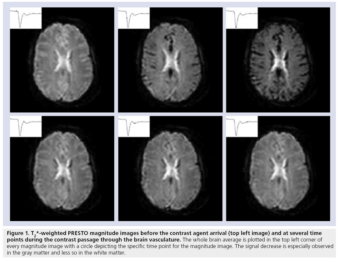
The actual signal drop observed in T2- and T2*-weighted magnitude images (Figure 1) is a combination of relaxation effects, diffusion of water protons over the local field changes and, for T2*-weighted images, dephasing due to the presence of local magnetic field changes [22]. The transformation from signal decrease to contrast agent concentration is important for accurate hemodynamic measurements.
Figure 1: T2*-weighted PRES TO magnitude images before the contrast agent arrival (top left image) and at several time points during the contrast passage through the brain vasculature. The whole brain average is plotted in the top left corner of every magnitude image with a circle depicting the specific time point for the magnitude image. The signal decrease is especially observed in the gray matter and less so in the white matter.
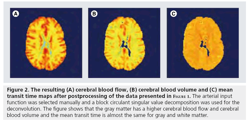
Having a correct concentration–time curve of the first passage of contrast agent through brain tissue is, however, not sufficient to calculate the hemodynamic parameters. Three of the hemodynamic parameters (CBF, CBV and MTT see Figure 2) can be obtained from the so-called impulse response function, which is mandatory for CBF and MTT estimations. The impulse response is the outcome of the hypothetical experiment of a d-injection of contrast agent in the brain-feeding artery. It describes the delay and broadening (dispersion) of this d-injection due to the transport through the vascular network. From the tracer kinetic theory, it can be shown that the maximum value of the impulse response function equals the CBF and the area under the curve equals the CBV. However, in clinical practice, the bolus is injected in the arm vein and the shape of the arterial input function (AIF), the concentration profile of a brain-feeding artery, is therefore much broader and is dependent on subject-specific transport properties between the injection site and the AIF measurement location and on the cardiac ejection fraction. The impulse response function can be obtained by deconvolving the tissue response with the AIF.
Figure 2: The resulting (A) cerebral blood flow, (B) cerebral blood volume and (C) mean transit time maps after postprocessing of the data presented in Figure 1. The arterial input function was selected manually and a block circulant singular value decomposition was used for the deconvolution. The figure shows that the gray matter has a higher cerebral blood flow and cerebral blood volume and the mean transit time is almost the same for gray and white matter.
In summary, DSC-MRI is based on the fast injection of contrast agent in the arm vein, whose passage through a brain-feeding artery (AIF) and brain tissue is monitored by fast dynamic MRI. Subsequently, the MR signal changes are converted to concentration–time curves and a deconvolution is performed; finally, the perfusion parameters are calculated from the impulse response function as based on tracer kinetics.
Contrast agent
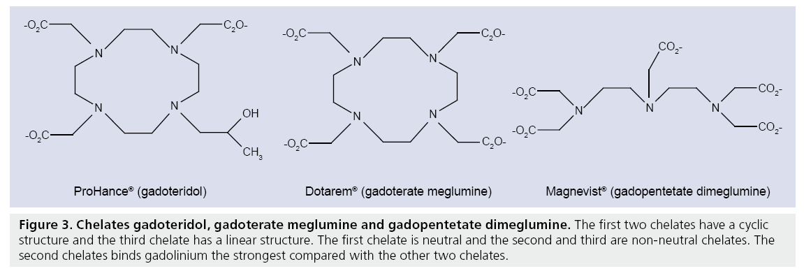
Most clinically approved contrast agents consist of a gadolinium ion (Gd3+) and a chelate to prevent toxic reactions in vivo. The first clinically approved contrast agent was gadolinium-diethylene triamine pentaacetic acid or gadopentetate dimeglumine (Gd-DTPA, Magnevist®, Bayer Schering, Berlin, Germany). Since the approval of Gd-DTPA for commercial use in 1988, many new chelates have been developed. DTPA has a linear chemical structure and is ionic (Figure 3). Until recently Gd-DTPA was most commonly used but recent studies have showed that chelates with linear chemical structures have a chance of transmetallation, the uncoupling of Gd3+ with the chelate, which can lead to nephrogenic systemic fibrosis in patients with reduced renal function [44,45]. New chelates with a cyclic structure such as gadoteridol (Prohance®), gadobutrol (Gadovist®) and gadoterate meglumine (Dotarem®) (Figure 3) reduce the chance of transmetallation. Furthermore, non-neutral chelates such as gadoterate meglumine bind the Gd3+ stronger than neutral chelates such as gadoteridol, thereby further reducing the chance of transmetallation.
Figure 3: Chelates gadoteridol, gadoterate meglumine and gadopentetate dimeglumine. The first two chelates have a cyclic structure and the third chelate has a linear structure. The first chelate is neutral and the second and third are non-neutral chelates. The second chelates binds gadolinium the strongest compared with the other two chelates.
The concentration of gadolinium can be 0.5 and 1.0 mol/l depending on the product. The increased concentration results in a lower volume to inject in the arm vein and this could lead to a shorter and sharper bolus with a higher peak concentration [46]. However, a later study showed no significant difference in peak width when comparing equal doses with different molarities [47].
The effects of the contrast agent on the MR signal are threefold: first, the susceptibility difference of the gadolinium-based contrast agent with blood results in local magnetic field changes in and around vessels. Second, the contrast agent decreases the transverse relaxation time of nearby water protons. Third, the contrast agent decreases the longitudinal relaxation time of nearby water protons.
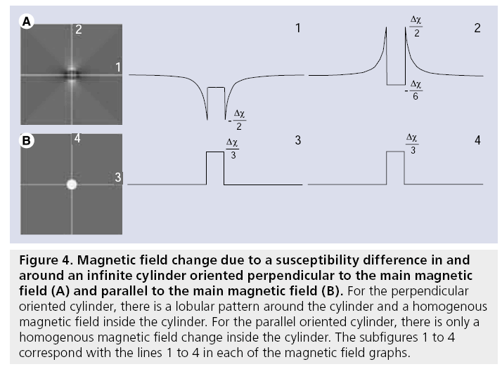
The intravascular susceptibility is linearly related to the concentration of contrast agent and changes the local magnetic field [48,49] in and around a vessel. For an infinite cylinder the local magnetic field changes due to the susceptibility difference can be obtained from the Maxwell equations (see also Figure 4):
Figure 4: Magnetic field change due to a susceptibility difference in and around an infinite cylinder oriented perpendicular to the main magnetic field (A) and parallel to the main magnetic field (B). For the perpendicular oriented cylinder, there is a lobular pattern around the cylinder and a homogenous magnetic field inside the cylinder. For the parallel oriented cylinder, there is only a homogenous magnetic field change inside the cylinder. The subfigures 1 to 4 correspond with the lines 1 to 4 in each of the magnetic field graphs.


where DBint is the magnetic field change inside the cylinder, DBext is the magnetic field change outside the cylinder, dc is the susceptibility difference per mol/l of gadolinium between the interior and exterior compartments, [Gd] is the concentration of gadolinium, a is the radius of the cylinder, ρ is the distance from any given point (p) to the cylinder center, φ; is the angle between the cylinder axis and B0, and f is the angle of p in the plane perpendicular to the cylinder axis. The interior magnetic field change for a parallel oriented cylinder is twice as strong compared with the magnetic field change for a perpendicular oriented cylinder and has opposite sign. Whereas a parallel cylinder does not change the magnetic field outside the cylinder, magnetic field changes outside the cylinder do occur for other orientations, where a pattern with positive and negative lobes can be observed.
For a voxel in tissue filled with randomly oriented capillaries the signal decrease as observed in T2*-weighted images is a result of susceptibility effects in and around the capillary network, diffusion through these magnetic field inhomogeneities and relaxation changes inside the vasculature [50]. A numerical study by Kjølby et al. showed that the susceptibility effects in the surrounding of the capillaries are the main cause of signal decrease in the magnitude images [51].
The concentration of contrast agent in the tissue can be determined by relating the signal intensity of the dynamic T2 (*)-weighted images to the signal intensity prior to the arrival of contrast agent. The equilibrium signal relation of gradient echo sequences is as follows:

where S(t) is the evolution of the magnitude of the MR signal, a is the flip angle, TR is the repetition time, T1(t) is the longitudinal relaxation time that will decrease during the contrast agent passage, TE is the echo time and T2*(t) the transverse relaxation time, which is also dependent on the contrast agent concentration. For sequences insensitive to longitudinal relaxation time changes, this relation simplifies to:

When using short TR sequences, as in principles of echo-shifting with a train of observations (PRESTO) or segmented EPI, T1 effects of the contrast agent can no longer be neglected when the flip angle is chosen close to the Ernst angle. Such effects do not only lead to erroneous quantitative CBF values, but also affect relative CBF measurements [52]. From theoretical and simulation studies it has been shown that the relation between the concentration of contrast agent in brain tissue and ΔR2* is linear with relaxivity r2*, whereas the ΔR2 has a slightly nonlinear relation with the contrast agent concentration [50,51,53,54]. The ΔR2 (*) is defined as:

with S(0) the magnitude signal before contrast agent arrival and T2 (*)(0) the T2 (*) without the presence of contrast agent. When acquiring more echoes, ΔR2* measurements can be obtained that are insensitive to T1 effects of the contrast agent [55–58]. Whereas spin-echo sequence are slower, show less signal changes for a certain contrast agent concentration and have a nonlinear relationship with the contrast agent concentration, it shows specific sensitivity towards the microvascular bed yielding perfusion maps less affected by large vessel artifacts [53].
Inside brain-feeding arteries the relation between the ΔR2* and the contrast agent concentration is more complex. In vitro experiments showed that the relation between the ΔR2* and the contrast agent concentration in human blood is quadratic and dependent on the hematocrit level [49,59]. This quadratic relation can be explained by the compartmentalization of the contrast agent within blood since the contrast agent remains extracellular. Based on the original Monte Carlo simulation study of Boxerman and coworkers, one might conclude that measurement of contrast agent concentration in or near a large vessel is not possible with spin-echo sequences, since these authors showed a vanishing sensitivity towards the presence of contrast agents for vessels larger than 30–50 μm [53]. However, based on measurements in pigs, it has been concluded that for AIF measurements a linear relation exists between ΔR2 and the contrast agent concentration [60,61].
Tracer kinetics
The method for determining the hemodynamic parameters CBF, CBV and MTT, as measured with DSC-MRI, is based on the classic tracer kinetic theory as developed by Zierler [62] and reviewed by Lassen [63]. The contrast agent concentration in the capillaries c(t) is dependent on the contrast agent concentration in the artery cAIF(t) supplying the blood to the tissue microvasculature (AIF) and the transport properties of the microvasculature itself. The output of the microvasculature, cout(t), can be expressed as a convolution of the AIF with a blood transport function h(t):

The blood transport function h(t) represents the distribution of transit times through the microvasculature. Under the assumption of an intact blood–brain barrier, all contrast agent will leave the microvasculature at some moment and therefore h(t) possesses the following property:

Following the same argument or by integration of Equation 6 in time leads to the following relation:

This is the basis of correction methods for partial volume artifacts of the AIF that rescale the AIF to have the same the area under the curve as the venous output function [64–66]. However, it should be noted that partial volume effects can also lead to shape changes, which are not corrected for in this approach (see section AIF measurements).
Dynamic susceptibility contrast MRI, however, does not measure the output of the microvascular system, but the amount of contrast agent still present in the tissue. Therefore, it is easier to describe the tracer kinetics in terms of the residue function ℜ(t), which describes the fraction of the contrast agent concentration that remains in the microvasculature after a d-injection contrast agent at the input of the microvasculature. The tissue residue function is equal to the impulse response normalized to unity. ℜ(t) can be deduced from h(t):

At the onset, this residue function has a value of one and this becomes zero when the contrast agent has completely washed out. The input to a voxel in the microvasculature ( nt (t) in in mol contrast agent) can be calculated from the AIF, when assuming that the AIF is not delayed nor dispersed during transport from the location of the AIF measurements towards the brain tissue:

where f is the blood flow in ml/s at the input of the voxel. The contrast agent concentration of a voxel in tissue is:

where equals the CBF except for some conversion factors.
The CBF can therefore be obtained by means of a deconvolution from the tissue passage curves and the AIF, when keeping in mind that ℜ (0)=1:

When the AIF was actually delayed by TA/s, then ℜ(t) will be zero for t<TA and will reach the value of one at TA s. Therefore, CBF is in practice not calculated from ℜ(0), but as the maximum value of ℜ(t):

whereas the timepoint of the maximum value of ℜ(t) is taken as TA. This method assumes that the applied deconvolution method handles delays correctly. This was not the case for the original singular value decomposition (SVD) method, but recent methods provide delay-insensitive results [67–70].
The CBV can be calculated from the product of the blood flow and the transport time function, comparable to the calculation of distance traveled from the product of velocity and time:

The CBV can also be calculated from the ratio of the areas under the curve of the tissue passage curve and the AIF, although this results in slightly worse quantification owing to difficulties in differentiating between the first passage and recirculation [71]. It should be noted that an additional correction for CBF and CBV is used to account for the difference in hematocrit in large (artery) and small (capillary) vessels.
Finally, the MTT of the blood through the capillary network can be calculated by using the central volume theorem, which describes the relation between CBF, CBV and the MTT [72,73].

As can be seen from Equation 14, the MTT can also be calculated by taking the area under the curve of the residue function.
AIF measurements
The AIF measurement is a crucial element for obtaining the hemodynamic parameters CBF, CBV and MTT with DSC-MRI. The AIF represents the concentration in time of the contrast agent through a brain-feeding artery (referred to as concentration profile). The concentration profile requires the AIF shape and peak height to be correctly measured to provide quantitative values for CBV, CBF and MTT. If the shape of the AIF is correctly measured, but the height is incorrect, then CBV and CBF will only show correct relative values, but MTT will still be quantitatively correct, since CBV and CBF will scale by the same factor. If the shape of the AIF is incorrect, all perfusion parameters calculated from the impulse response function will be incorrect, although relative CBV values can be obtained from the area under the curve of the tissue response. AIF selection is often performed manually but a number of automatic selection procedures have been proposed based on shape characteristics of a correct AIF, such as high peak height, small full-width-half-maximum, low first moment and steep rise [74–76].
Initial approaches to measure the AIF with both correct height and shape concentrated on finding voxels located completely inside a brainfeeding artery. In this case a quadratic relaxation rate for magnitude-based AIF measurements should be used and a linear relation for phasebased AIF measurements [49,59,77]. At an optimal dose and echo time phase-based AIF measurements have increased signal-to-noise ratio (SNR) compared with magnitude-based AIF measurements [78,79]. However, phase-based AIF measurements still require a magnitude-based estimation of the brain tissue response, because the contrast agent induces almost no phase changes in a voxel filled with randomly oriented capillaries [80]. Owing to the high maximum concentration of the AIF (~15 mM), the MR signal can drop into noise level, which would corrupt the shape of the concentration profile independent of whether the amplitude or the phase of the MR signal is used for the measurement. Reducing the echo time or lowering the contrast agent dose could prevent signal depletion, but both methods would result in a lower SNR of the tissue response measurement. Therefore, dual echo approaches have been proposed with a short echo time for the AIF measurement and a longer echo time for the tissue response [55]. An additional advantage of dual echo sequences is that longitudinal relaxation effect can be compensated for [58,81].
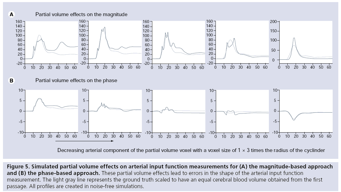
The AIF can theoretically be measured correctly in a voxel located completely within an artery, but owing to the limited spatial resolution of DSC-MRI, such voxels cannot be found in actual experiments and partial volume effects can therefore not be avoided. Owing to mixing of the arterial signal with the signal from the surrounding tissue, nonlinear distortions of the AIF can occur when gradient echo imaging is employed. These distortions occur because the phase evolution of the arterial compartment will differ from the phase evolution in the surroundings, leading to in- and out-of-phase effects depending on the contrast agent concentration. Partial volume effects affect both the magnitude- and phase-based AIF measurements and can attain different manifestations, as shown in Figure 5. AIF shape distortions due to partial volume effects can only be corrected for arteries parallel to the main magnetic field, because only in this orientation are magnetic field changes not present in the surrounding tissue when the contrast agent passes through the artery (Figure 4) [82].
Figure 5: Simulated partial volume effects on arterial input function measurements for (A) the magnitude-based approach and (B) the phase-based approach. These partial volume effects lead to errors in the shape of the arterial input function measurement. The light gray line represents the ground truth scaled to have an equal cerebral blood volume obtained from the first passage. All profiles are created in noise-free simulations.
Since AIF measurements in voxels located in or near the artery are hampered by these partial volume effects, the AIF is often selected in tissue surrounding the artery. When the artery is not oriented parallel to the main magnetic field, the magnetic field outside the artery will also change due to the passage of the contrast agent within the vessel. These magnetic field changes lead to changes in the phase and amplitude of the MR signal of tissue surrounding the vessel, which can therefore be used to estimate the AIF. Voxels located close to the vessel wall but completely outside the artery are unaffected by partial voluming with arterial signal, but still show reasonably large signal changes during the arterial bolus passage. Numerical modeling has shown that at specific locations outside an artery a correct measurement of the shape of the AIF can be obtained using either the magnitude or the phase of the MR signal [83–85]. A disadvantage of measuring the AIF in tissue surrounding an artery is that such measurements will be affected by the tissue response of the same voxel. Thornton et al. proposed subtraction of the tissue response to improve the magnitudebased AIF measurements [86]. Phase-based AIF measurements have almost no tissue response and are therefore only affected slightly by the tissue passage.
Traditionally, a single (global) AIF is used for all voxels in the brain tissue and such a global AIF is frequently measured in the internal or middle cerebral artery. However, these arteries are located at a relatively large distance from the microvasculature. All dispersion between these arteries, where the AIF is measured and the actual input of the microvasculature, would be incorrectly interpreted as microvascular dispersion and thus lead to quantification errors in the CBF [68]. Thijs et al. showed for example that for stroke patients the AIF is best selected on the contralateral side of the infarct [87]. Based on the original ideas of Alsop et al., several investigators have looked into the possibility of estimating an individual AIF for every tissue voxel [88]. Such ‘local’ AIFs would be much less affected by dispersion effects. Independent component analysis, factor analysis and feature extraction have been proposed for obtaining local AIF measurements [88–91]. The benefit of reduced dispersion effects for local AIFs comes with potential disadvantages, such as increased risk of partial volume effects [92] and a reduced SNR.
Deconvolution
A correct AIF and tissue response still require a deconvolution approach to produce the impulse response from which the CBF, CBV and MTT are derived. There are two general approaches for deconvolution: model-dependent approaches [93–96] and model-independent approaches [69,97,98]. The model-independent approaches are rarely dependent on the underlying vasculature but can be sensitive to noise and dispersion of the bolus. Dispersion effects lead in general to an underestimation of CBF and hence an overestimation of MTT [68]. The effect of dispersion is excellently reviewed by Calamante [99]. Furthermore, the original (also referred to as standard) SVD approach was sensitive to delay effects [69]. The simplest model employed for model-dependent approaches is an exponential decay; this model describes the microvasculature as a single well-mixed compartment. Models that are more complex can describe, to some extent, delay and dispersion, but with additional parameters fitting the residue function becomes more difficult. Moreover, if the model is different from the true vascular response the obtained hemodynamic parameters have erroneous values.
Currently, most postprocessing methods of DSC-MRI rely on model-independent deconvolution techniques that do not pose restrictions on the shape of the impulse response. A number of different model-independent deconvolution approaches have been reported, for example the SVD and block-circulant SVD (which is a modified version of the SVD in order to make the deconvolution delay insensitive) [67,69,70] or the Tikhonov regularization [100]. A different approach is the Fourier-based deconvolution, where deconvolution is a mere division [97,101]. Deconvolution can also be performed using a statistical approach such as the maximum likelihood estimation maximization (MLEM) and its modified version mMLEM (in order to make the deconvolution less sensitive to delay and dispersion) [98,102,103].
All deconvolution methods are susceptible to noise on the tissue response and the AIF. Noise on the concentration profiles can corrupt the outcome of the deconvolution and therefore each deconvolution method employs some kind of filtering, either by spectral filtering [96,97], cutoff value on the eigenvalues of the matrix inversion [69,104] or by limiting the number of iterations in iterative methods [98,102].
Arterial spin labeling
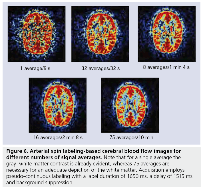
Arterial spin labeling is a completely noninvasive perfusion imaging technique that employs water protons as an endogenous tracer to probe the blood supply to tissue [23,105]. Since water transport across the blood–brain barrier is relatively unrestricted, water protons are considered diffusible (although not completely freely diffusing) tracers [23,106–109]. Labeling is performed at the location of the larger brain-feeding arteries such as the internal carotid artery or the basilar artery and after labeling a delay is inserted in the sequence to allow the labeled spins to travel towards the microvasculature. The spin of water protons located in the brain-feeding arteries are either inverted [23] or saturated [110,111] by a RF pulse. The imaging performed after the labeling is proton density weighted, with a short echo time to limit the influence of transverse relaxation. Since such images are not only sensitive to the inflow of labeled spins, but also to signal from static tissue, a second image is acquired without labeling arterial blood. A subtraction of the label from the control image provides an image that is only sensitive to the presence of labeled spins. Such a single subtraction image is, however, of limited quality and therefore 30–60 averages are usually obtained to increase SNR (Figure 6). In the following sections the labeling, the imaging and quantification of the CBF are discussed. Furthermore, ASL provides the opportunity to label only a single artery, thus potentially allowing the flow territory of a single vessel to be imaged. This has importance in pinpointing the origin of emboli in acute stroke [112], differentiating en passage feeders from direct feeders in arterio–venous malformation and in understanding collateral blood flow in large vessel disease [28,29,113,114]. The different approaches of flow territory mapping will also be discussed.
Figure 6: Arterial spin labeling-based cerebral blood flow images for different numbers of signal averages. Note that for a single average the gray–white matter contrast is already evident, whereas 75 averages are necessary for an adequate depiction of the white matter. Acquisition employs pseudo-continuous labeling with a label duration of 1650 ms, a delay of 1515 ms and background suppression.
Labeling of arterial blood
Labeling approaches for ASL can be subdivided into three categories: continuous ASL (CASL), pulsed ASL (PASL) and velocity selective ASL (VSASL). These three categories differ based on the temporal layout of the sequence and the spatial extent of the labeling sequence. ASL is a subtraction technique based on the assumption that the only difference between the label and control image originates from the inflow of labeled spins. When designing a labeling approach it is therefore essential that the influence on the spins in the imaging slices is equal for the label and control module. In this respect, it is essential to avoid magnetization transfer (MT) effects (see next section).
MT effects
All labeling approaches employ slice selective RF pulses to invert or saturate water spins at the labeling location. Whereas water protons in blood have a narrow frequency spectrum, the frequency spectrum of macromolecules in brain tissue is much broader. Therefore, slice selective RF pulses of the labeling module do still affect macromolecular spins even when they are located at a different location along the slice selection gradient and this magnetization can be transferred to the free water signal. When the total power of RF pulses in the labeling part of the sequence differs from the control part, a net difference in magnetization will be created that will show as subtraction errors in the ASL CBF images. For some ASL implementation the occurrence of this type of error is easily tested by labeling the superior from the imaging slices instead of the neck region (e.g., in [115]).
Continuous ASL
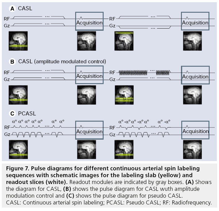
In CASL, labeling is performed using a small labeling plane through the brain-feeding arteries (Figure 7). The water protons that flow through that labeling plane are inverted using a flowdriven adiabatic inversion RF pulse in combination with a small gradient in the flow direction [23,116,117]. The labeling is switched on for a relatively long period of 1.5–2.5 s to create sufficient labeling resulting in a long bolus of labeled blood. Owing to the continuous RF pulse, the total RF power is high, thereby potentially leading to severe MT effects. To avoid such MT effects, the control image needs to have the same RF power with minimal effect on the magnetization of arterial blood. Two different approaches have been proposed: the first approach limits the coverage to a single plane, by changing the position of the labeling plane to the other side of the imaging plane. When extending the coverage to more than a single plane, this approach would result in slightly asymmetrical excitation of the macromolecules for the control and the label part, which will lead to subtraction errors. Therefore, a second approach has been proposed that employs amplitude modulation of the RF pulse for the control images to create two inversion planes close to each other, thereby resulting in a double inversion of the blood flowing through these planes. The last approach is currently the most common implementation of CASL, although the double inversion plane approach results in a slightly lower labeling efficiency of approximately 80%.
Figure 7: Pulse diagrams for different continuous arterial spin labeling sequences with schematic images for the labeling slab (yellow) and readout slices (white). Readout modules are indicated by gray boxes. (A) Shows the diagram for CASL, (B) shows the pulse diagram for CASL wuth amplitude modulation control and (C) shows the pulse diagram for pseudo CASL. CASL: Continuous arterial spin labeling; PCASL: Pseudo CASL; RF: Radiofrequency.
Advantages of CASL are that all spins are labeled at the same level of the arterial tree and that the temporal width of the bolus is determined by the labeling duration. Both characteristics result in a straightforward quantification of the CBF as long as all labeled spins have reached the microvasculature in the imaging volume before the start of the readout [118,119]. Disadvantages of CASL are the difficult implementation of the continuous RF pulse on modern RF amplifiers and the relatively high specific absorption rate (SAR) of the sequence.
Pseudo or pulsed CASL (PCASL) was recently proposed to reduce the demands on the RF amplifier and to lower the SAR while keeping the advantages of CASL [120–122]. PCASL splits the continuous RF pulse of CASL into a train of short, slice selective RF pulses that gradually invert the spins of the water protons when combined with a small net gradient along the artery. As a control scan, the amplitude of the odd pulses can be inverted or the net gradient can be nulled. It has been shown that the labeling efficiency of PCASL can be higher than the amplitude-modulated CASL implementation, although the sequence is sensitive to offresonance effects and the efficiency depends on the arterial velocity [120,122].
Pulsed ASL
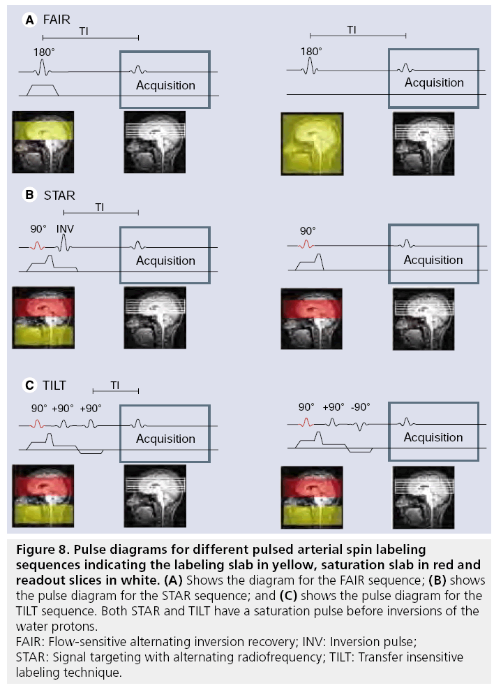
The labeling approach in PASL is fundamentally different from the CASL approach: instead of a temporally long but spatially confined labeling pulse, a short labeling pulse is employed over a large region. Although the labeling period is short, in the order of 10–15 ms, a large amount of spins can still be labeled, since a much larger part of the brain-feeding vasculature is labeled. Many different approaches have been proposed for PASL, although in the end all implementations create a situation in which spins proximal to brain vasculature have an opposite magnetization during labeling compared with the control situation [123–133] (see overview in [134]). Three of the best-known PASL sequences are flowsensitive alternating inversion recovery (FAIR), signal targeting with alternating radiofrequency (STAR) and transfer insensitive labeling technique (TILT) (Figure 8). FAIR employs a sliceselective inversion of the imaging slices as a label condition and a nonselective inversion pulse in the control situation. STAR and TILT are both based on a slice-selective inversion below the imaging slices, where STAR employs no RF pulses for the control image and TILT uses a +90 and -90 pulse as control.
Figure 8: Pulse diagrams for different pulsed arterial spin labeling
sequences indicating the labeling slab in yellow, saturation slab in red and
readout slices in white. (A) Shows the diagram for the FAIR sequence; (B) shows
the pulse diagram for the STAR sequence; and (C) shows the pulse diagram for the
TILT sequence. Both STAR and TILT have a saturation pulse before inversions of the
water protons.
FAIR: Flow-sensitive alternating inversion recovery; INV: Inversion pulse;
STAR: Signal targeting with alternating radiofrequency; TILT: Transfer insensitive
labeling technique.
Advantages of PASL are the high labeling efficiency and the lower SAR due to the short RF pulses. Disadvantages are the potentially lower SNR of the CBF images and difficulties in quantification, because labeling is performed spatially, thereby incorporating a dependency on the layout of the arterial tree.
Velocity selective ASL
Whereas both CASL and PASL differentiate flowing arterial blood from static tissue signal by spatially limiting the labeling to the region below the imaging slice, VSASL differentiates flowing from stationary spins by employing flow-encoding gradients. In the label condition spins that flow faster than approximately 2 cm/s are saturated, whereas only minimal flow-sensitive components are used in the control condition [111]. Since arterial blood flow is gradually slowing when flowing from brainfeeding arteries into the microvasculature and venous blood is accelerating when leaving the microvasculature, this approach enables discrimination of arterial and venous signal. Flow encoding can be performed in the imaging slab, thereby labeling the arterial blood much closer to the microvasculature and thus minimizing transport times of the labeled spins. However, comparable to PASL it is ill-defined how much spins are exactly labeled, thereby making accurate quantification difficult.
Readout approaches for ASL
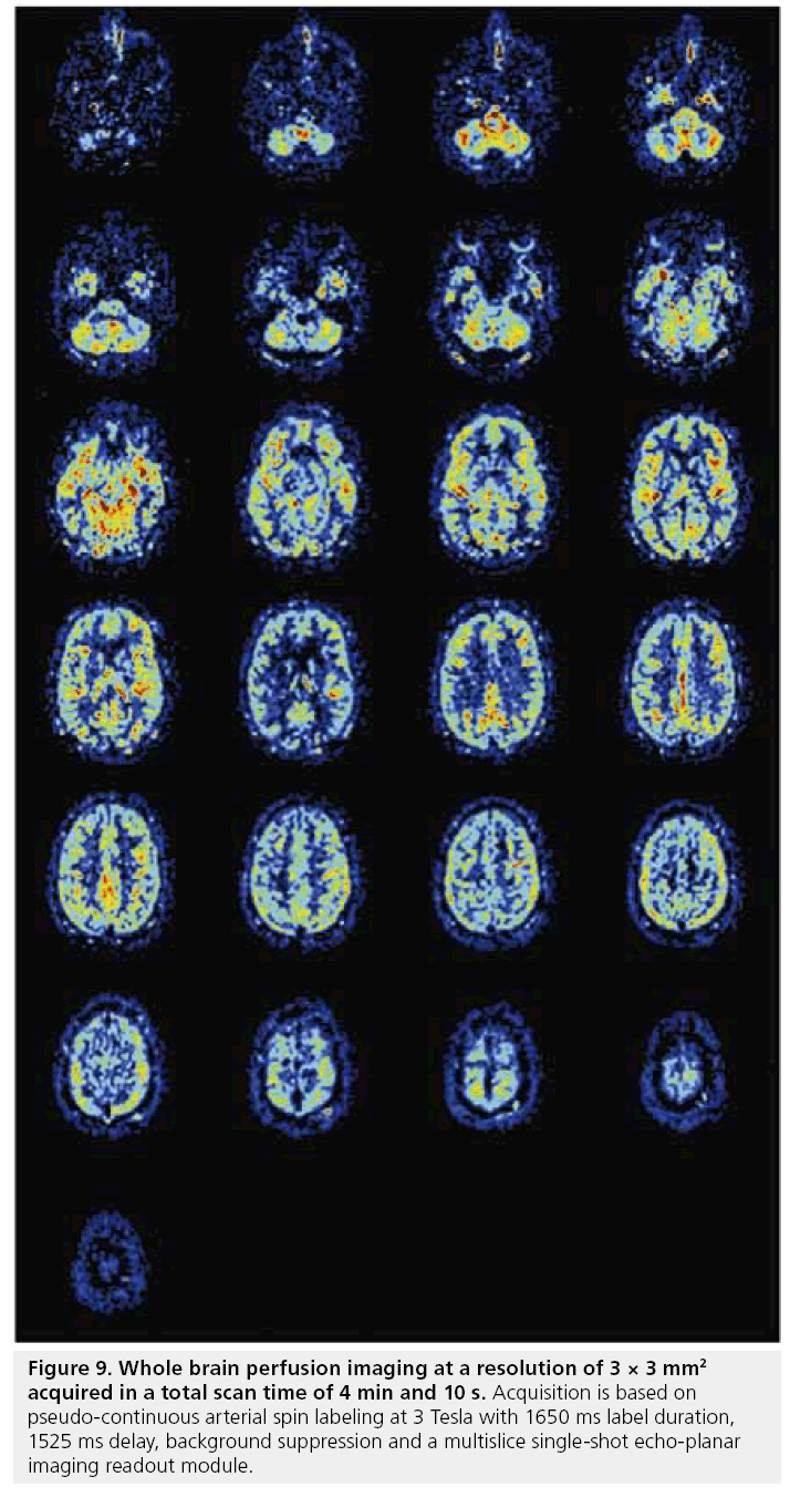
In principle, any readout sequence can be used for ASL as long as the sequence is predominantly proton density weighted. However, since the combination of labeling and delay times are time-consuming (at least 1.5 s), the imaging sequence should enable all image data to be acquired after a single (or a few) labeling periods. Single-shot EPI or fast low-angle shot (FLASH) readout sequences are therefore the most commonly used readout protocols [134–136]. With the recent advances in gradients performance and the introduction of parallel imaging, it has become feasible to acquire whole brain perfusion images at a resolution of 3 × 3 mm2 within a total readout time of 900 ms, thereby resulting in high quality perfusion images in 4 min (Figure 9). More recently, the application of True-FISP as a readout module for ASL has been investigated [137–139].
Figure 9: Whole brain perfusion imaging at a resolution of 3 × 3 mm2 acquired in a total scan time of 4 min and 10 s. Acquisition is based on pseudo-continuous arterial spin labeling at 3 Tesla with 1650 ms label duration, 1525 ms delay, background suppression and a multislice single-shot echo-planar imaging readout module.
Traditionally, CASL has been frequently combined with spin-echo EPI and PASL with gradient- echo EPI. However, the choice of readout sequence does not depend on the type of labeling module, but only on the clinical research question. For example, in the lower brain, spinecho sequences provide better image quality than gradient-echo sequence at the expense of slower imaging. Recently, 3D single (or multishot) acquisition methods (GRASE) have gained much attention for two reasons; first, 3D sequence have an inherently higher SNR than multislice sequences; and second, all blood flow information is acquired at exactly the same moment [140]. This last issue avoids modulation of the blood flow information by different transport times for different slices and enables perfect background suppression for the complete volume (see next section).
Background suppression
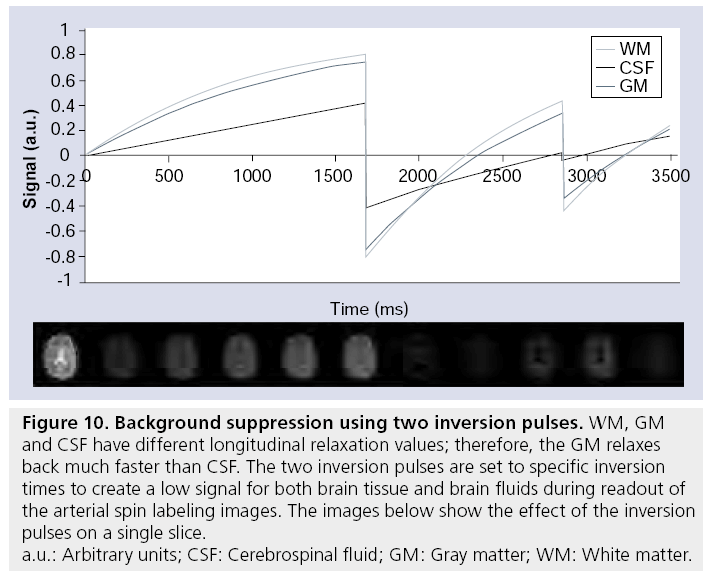
All implementations of ASL use a subtraction to separate the signal from static tissue from the perfusion signal. Since CBV is less than 5%, the perfusion signal is more than a factor of 20 smaller than the signal from static tissue. This implies that a few percent signal fluctuations of the static tissue signal are of the same order of magnitude as the perfusion signal. Physiological noise caused by the respiratory cycle, for example, can result in such signal f luctuations, thereby degrading the SNR of the ASL. When the relative signal contribution of static tissue and perfusion signal would be more comparable, the influence of such signal fluctuations on the SNR of ASL images would decrease considerably. This is the basis of the so-called background suppression – by including additional nonselective inversion pulses prior to the readout module, background signal of static tissue can be nulled during acquisition (Figure 10) [141]. Although nulling of the background signal would in principle leave exclusively the signal of the labeled spins, nulling of all tissue components cannot be achieved and to avoid uncertainties in the sign of the magnetization of these residual components, a small positive residual signal of approximately 5–10% is aimed for. For multislice sequences, background suppression will be optimal for the first slice, but gradual regrow of the static tissue magnetization will result in suboptimal background signal for subsequent slice
Figure 10: Background suppression using two inversion pulses. WM, GM
and CSF have different longitudinal relaxation values; therefore, the GM relaxes
back much faster than CSF. The two inversion pulses are set to specific inversion
times to create a low signal for both brain tissue and brain fluids during readout of
the arterial spin labeling images. The images below show the effect of the inversion
pulses on a single slice.
a.u.: Arbitrary units; CSF: Cerebrospinal fluid; GM: Gray matter; WM: White matter.
Quantification of CBF by ASL
After subtraction of the label from the control image, an image is obtained that reflects the amount of labeled spins present in the tissue at the moment of imaging. Since MRI provides only arbitrary numbers, the values from the subtraction image should be normalized. This is often referred to as the M0 measurement and the different approaches to obtain this calibration factor are discussed later. Although information on the cerebral perfusion is included in the calibrated subtraction image, other factors affect the amount of detected labeled spins, such as the input function (that is the amount of labeled spins), loss of label due to longitudinal relaxation while the spins reside in the blood and tissue compartment, loss of signal due to transversal relaxation and imperfect excitation pulses. These different factors will be discussed in the following sections.
M0 measurement
Quantification of the CBF by ASL is based upon the idea of creating a label in brain-feeding arteries and to monitor what brain tissue is fed by this label. Therefore, the signal intensities in the subtraction image should be compared with the signal intensity of pure blood, which is the maximal signal that could be obtained if a perfectly created label filled a complete voxel. The first step in quantification of ASL images is therefore to normalize the signal intensities of the subtraction image by M0, the signal intensity of pure blood in a proton density sequence. To measure M0, several approaches have been proposed, all based on the measurement of the MR signal intensity in reference areas, such as the ventricles and sagittal sinus, or by employing the signal intensity of the control images as a reference. Except for the sagittal sinus, all other approaches need correction factors to compensate for differences in proton density, for example between cerebrospinal fluid and blood [142]. When measuring the M0 of brain tissue in the control images, division by the brain–blood partition coefficient (frequently represented by λ = M0 brain tissue/M0 blood .0.9 [143]) needs to be performed to obtain M0blood. When using M0brain tissue, differences in proton density in gray and white matter or pathology will bias the CBF values, although on the other hand differences in coil sensitivity profiles are automatically compensated for. Measurements in smaller regions-of-interest such as the sagittal sinus or the ventricles are known to introduce a considerable amount of noise in the quantification, thereby limiting the usefulness of these calibration methods. Suboptimal measurement of M0 is probably still one of the main sources of quantification errors in ASL [144].
Input function of labeled spins
As a second step in the quantification process, the temporal profile of the bolus of labeled spins that leave the labeling area has to be known, which is determined by the labeling efficiency and the temporal-spatial layout of the labeling pulses. Since almost all ASL methods (except VSASL) create an inversion difference between label and control, the maximum difference between label and control equals two times M0 (e.g., +M0 vs -M0). For PASL an almost perfect labeling efficiency can be obtained by using adiabatic inversion pulses that provide a proper inversion over a large area, independent of local B0 and B1 inhomogeneities [145]. However, such adiabatic inversion pulses do lead to some efficiency losses due to transverse relaxation. For CASL and PCASL the labeling efficiency will be approximately 20% lower and show a slight dependency on the arterial flow velocity. Estimates of the labeling efficiency, frequently represented by α, have been obtained by using single-slice CASL as reference or by simulations of the Bloch equations [116,117,119,122]. Finally, it has recently been proposed that a separate phase contrast quantitative flow sequence in combination with an estimation of the total brain volume be used to estimate the labeling efficiency and thereby normalizing the CBF maps [146]. When an estimate of the labeling efficiency is obtained, the difference image is be divided by this factor to correct for the imperfect labeling efficiency.
Continuous ASL and PCASL perform the labeling at a single position in the brain-feeding arteries for a period of 1–2 s. This implies that the input function can be considered to be a block-function with an amplitude of α and a temporal width equal to the labeling duration.
This width will be equal for all labeled vessels, although a might be variable for different arteries. For PASL the input function is more complicated, since labeling is performed over a much larger region of the arterial tree (Figure 8). The temporal width of the input function when it leaves the upper part of the labeling slab will be determined by the length of the vessels within the labeling slab and the blood velocity therein. The input function will be different for different vessels owing to these dependencies. Furthermore, spins that are labeled more proximal in the arterial tree will leave the labeling later and during this transport delay, some label will be lost due to longitudinal relaxation. The input function will therefore have an exponential decreasing shape. Finally, the slice profile of the inversion pulses will modulate the shape of the input function. This can be especially important for the most proximally labeled spins, where the slice profile can be affected by the coil transmit profile [147,148]. In particular, because of the uncertainties in the temporal width of the input function in PASL, quantification becomes challenging. To circumvent this issue, three different solutions have been proposed.
First, Wong and coworkers have proposed to cut off the input function by means of a saturation pulse at the labeling location shortly (~800 ms) after the inversion pulse [125]. When not all inverted spins have left the labeling slab, this implies that the width of the input function has been fixed to the same duration (e.g., 800 ms). However, the width of the input function would still be undetermined when the saturation pulse is played out too late, for example all labeled spins of a certain artery have already left the labeling slab. A correct choice of the timing of the saturation pulse is therefore essential: when chosen too early, only very few spins have been labeled, whereas a saturation pulse applied too late will no longer fix the width of the label bolus. This approach is named QUIPSS-II and can be combined with most PASL approaches. When the saturation pulse is replaced by a train of saturation pulses with a smaller slice thickness, the approach is named Q2TIPS [149].
Second, instead of influencing the shape of the input function, the width can also be estimated by monitoring the signal evolution over time in the brain tissue. In this approach, images are not acquired at a single delay time as is usually performed with ASL, but a series of images with different delay are acquired [118,131,150]. In such an approach images will be acquired directly (100 ms) after labeling until most signal is lost (~3000 ms after labeling) at a 150–300 ms interval. Modeling of the signal–time curves results indirectly in an estimate of the width of the input function.
Finally, it is possible to incorporate the measurement of the shape of the input function into the ASL sequence [151,152]. This shape can be obtained by subtracting an ASL image with vascular crushing (tissue signal) from an ASL image without crushing of fast-flowing spins (tissue plus arterial signal). Since this approach needs to acquire images with and without vascular crushing, the sequence will last longer than conventional approaches. After obtaining the correct shape of the input function, this knowledge is incorporated into the analysis, thereby enabling an improved quantification of the CBF.
Transport of the label towards the brain tissue
After leaving the labeling slab, the labeled spins will be transported to the microvasculature. These transport times can be different for different brain regions and may vary, especially in patients with vascular occlusive disease. While residing in blood, the label as encoded in the longitudinal magnetization will decay due to longitudinal relaxation. When the transport time is longer than the delay in the sequence, not all labeled spins will have arrived in the brain tissue when imaging, leading to an underestimation of the perfusion. Errors due to prolonged transit times are especially prominent in patients with large vessel disease, and multi-TI approaches have been used to correct for this.
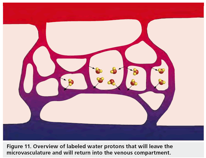
When the capillaries are reached, the label will start to cross the blood–brain barrier and exchange with the brain tissue [109]. Finally, the label will also leave the tissue into the venous compartment (Figure 11). While the label resides in the brain tissue, it will no longer decay with the T1 of blood, but with the T1 of tissue. The fact that decay of the label differs according to which compartment the label resides complicates quantification, but fortunately the longitudinal relaxation times of blood and tissue are comparable and most commonly a single T1 is assumed. However, several researchers have investigated how this assumption affects quantification [106,107,109]. From these studies it can be concluded that the error made by this so-called single compartment assumption are smaller for PASL than for CASL and more prominent for white than gray matter for low perfusion values.
Transverse decay of signal
Except for spiral readout approaches, all imaging modules employed in ASL result in T2 or T2* decay of the signal after the excitation pulse [153]. Whereas most researchers will assume a single reference value for T2* and employ a correction factor when converting the signal intensities to CBF values, this assumption might breakdown regionally, in pathology or when monitoring CBF changes upon brain activation. In particular, in the frontal areas and above the petrous bones, magnetic field inhomogeneities result in a much shorter T2* than in more homogenous brain tissue [154]. This can result in an underestimation of the regional CBF by 30%. In a preliminary study employing a dual-echo readout module, we have further shown that T2* changes upon activation have only marginal effects in ASL [154]. This implies that the ASL signal originates predominantly from the arterial side of the microvasculature, whereas blood oxygen level dependent (BOLD) effects are on the venous side. Dual-echo ASL sequences can therefore be used to monitor simultaneously CBF changes (first, short TE) and BOLD (second, long TE) [155,156].
Taking it all together: the Buxton model
Buxton and coworkers were among the first to describe a model of ASL that includes most terms affecting ASL perfusion quantification. This model was dubbed the general kinetic model, but has recently become better known as the ‘Buxton model’. The simplest version of the general kinetic model consists of three functions: the input function of labeled spins at the tissue level (cinput); the residue function describing how long labeled water molecules will stay in the tissue voxel (r(t)=exp(-f·t/λ)); and the magnetization relaxation function (m(t)=exp(-t/T1)), which describes the loss of label due to longitudinal relaxation. The only difference between PASL and CASL is in the shape of the input function at the entrance of the tissue, reflecting the difference in travel times of labeled water molecules in PASL depending on the localization within the label slab:
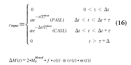
with Dt equaling the transit delay and t the fresh inflow time (PASL) or labeling duration (CASL or QUIPSS). This model is the basis for multi-TI ASL measurements, which are based on fitting Equation 16 to measured ASL difference signal at multiple delay times.
Imaging artifacts
B1 variations are especially eminent at medium (3 Tesla) and higher magnetic field strengths (e.g., 7 Telsa). Any variation in B1 deposition will result in deviations from the perfect 90° excitation pulse and will result in a modulation of the CBF map. By acquiring images at multiple flip angles, this effect can be corrected for, although at the expense of a time penalty [152]. Furthermore, variations in the received profile of the reception coil can result in erroneous CBF maps, although coil sensitivity profiles are now frequently measured and corrected for as part of the implementation of parallel imaging. Finally, it should be noted that using fast sequences can result in distortions or blurring of the CBF maps. By limiting the readout time of the sequence, for example by parallel imaging, such distortions and blurring can be minimized. Single-shot 3D sequences bare the risk of significant blurring in the z-direction owing to T2 decay of the signal during the long readout.
Flow territory imaging
In the last decade, flow territory mapping based on ASL methods has gained much attention, especially since the only alternative for flow territory mapping by ASL is the invasive method of conventional catheter angiography with the associated mortality and morbidity. The principal idea of flow territory mapping is to restrict the labeling pulses to a single artery, thereby exclusively imaging the tissue supplied by this artery. Several different approaches have been proposed to limit the labeling to a single artery, such as:
▪ Separate labeling coil; by positioning a small labeling coil on top of a vessel, the RF is limited to this vessel and the labeling will therefore also be restricted to this artery [157–159]. This method is easily implemented, although it relies on separate hardware and yields only limited flexibility in which arteries can be labeled during a single session;
▪ Tilting of labeling plane; whereas traditionally ASL labeling planes are always in the transverse orientation, this labeling plane can also be tilted and positioned in such a way that only a single vessel is labeled [129,160]. After tilting the labeling plane, the plane could intersect with the imaging slices and therefore it is essential that saturation pulses before and after labeling are included in the sequence to circumvent artifacts in the subtraction images. Second, it can be challenging to plan this tilted plane in such a way that only a single vessel is labeled. This method is therefore mainly used to differentiate between left and right internal carotid artery flow territories and posterior circulation;
▪ For CASL and PCASL the gradient in the flow direction of vessel can be rotated during labeling to limit labeling to a single spot in the labeling plane [161]. This approach enables superselective labeling of the smallest vessels. For CASL this method can result in artifacts in the imaging slices, but for PCASL this issue does not occur, since the rotating gradients are played in between the RF pulses [162];
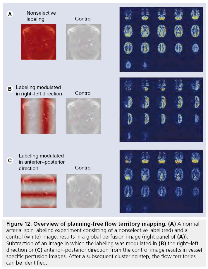
▪ Wong and coworkers have developed a planning- free method for flow territory mapping, which is based on the acquisition of four or more images with different labeling distribution over the different brain-feeding arteries (Figure 12) [163–166]. The first two images are the control and label images of a normal ASL experiment and subtraction of these two images results in a normal nonselective perfusion map. In the following images the labeling efficiency is varied in the right–left or anterior–posterior (or any other) direction (Figure 12B & C). Subtraction of these images from the control image and normalizing with respect to nonselective perfusion map results in a relative labeling efficiency map. Based on clustering methods, regions are identified that have comparable relative labeling efficiency independent of how the labeling efficiency of the arteries is changed.
Figure 12: Overview of planning-free flow territory mapping. (A) A normal arterial spin labeling experiment consisting of a nonselective label (red) and a control (white) image, results in a global perfusion image (right panel of (A)). Subtraction of an image in which the labeling was modulated in (B) the right–left direction or (C) anterior–posterior direction from the control image results in vessel specific perfusion images. After a subsequent clustering step, the flow territories can be identified.
Conclusion & future perspective
Both DSC-MRI and ASL are becoming important tools in the radiological clinic and both perfusion methods are considered essential for many different clinical indications, such as brain tumors and acute stroke. Furthermore, ASL is starting to play an important role in psychological research since it enables PET-like studies of the cognitive state of subjects. Both methods will continue to benefit from hardware improvements, such as techniques for parallel transmission and reception, improved coil design and higher magnetic field strengths. These developments will continue to provide improved new insights in the cerebral hemodynamics. In the coming years quantification of cerebral perfusion will remain the most challenging part of both MRI techniques and more research is definitely needed to obtain absolute quantification of the CBF and CBV. Finally, it is anticipated that reactivity measurements, that is relative blood flow changes upon a vasodilatory challenge such as acetazolamide or breath-holding, will improve the hemodynamic characterization of neurodegenerative disease.
Financial & competing interests disclosure
The authors’ work is supported by the Dutch Technology Foundation (STW: grant 7291). The authors have no other relevant affiliations or financial involvement with any organization or entity with a financial interest in or financial conflict with the subject matter or materials discussed in the manuscript apart from those disclosed.
No writing assistance was utilized in the production of this manuscript.

References
- Christensen S, Mouridsen K, Wu O et al.: Comparison of 10 perfusion MRI parameters in 97 sub-6-hour stroke patients using voxel-based receiver operating characteristics analysis. Stroke 40(6), 2055–2061 (2009).
- Emblem KE, Zoellner FG, Tennoe B et al.: Predictive modeling in glioma grading from MR perfusion images using support vector machines. Magn. Reson. Med. 60(4), 945–952 (2008).
- Lemort M, Canizares-Perez AC, Van der Stappen A, Kampouridis S: Progress in magnetic resonance imaging of brain tumours. Curr. Opin. Oncol. 19(6), 616–622 (2007).
- Provenzale JM, Shah K, Patel U, McCrory DC: Systematic review of CT and MR perfusion imaging for assessment of acute cerebrovascular disease. Am. J. Neuroradiol. 29(8), 1476–1482 (2008).
- Theberge J: Perfusion magnetic resonance imaging in psychiatry. Top. Magn. Reson. Imaging 19(2), 111–130 (2008).
- Wintermark M, Fiebach J: Iodinated and gadolinium contrast media in computed tomography (CT) and magnetic resonance (MR) stroke imaging. Curr. Med. Chem. 13(22), 2717–2723 (2006).
- Aronen HJ, Perkio J: Dynamic susceptibility contrast MRI of gliomas. Neuroimaging Clin. N. Am. 12(4), 501–523 (2002).
- Folkman J, Klagsbrun M: Angiogenic factors. Science 235(4787), 442–447 (1987).
- Derdeyn CP, Videen TO, Yundt KD et al.: Variability of cerebral blood volume and oxygen extraction: stages of cerebral haemodynamic impairment revisited. Brain 125(Pt 3), 595–607 (2002).
- Derdeyn CP, Powers WJ, Grubb RLJ: Hemodynamic effects of middle cerebral artery stenosis and occlusion. AJNR Am. J. Neuroradiol. 19(8), 1463–1469 (1998).
- Liebeskind DS: Collateral circulation. Stroke 34(9), 2279–2284 (2003).
- Hendrikse J, Hartkamp MJ, Hillen B, Mali WP, van der Grond J: Collateral ability of the circle of Willis in patients with unilateral internal carotid artery occlusion: border zone infarcts and clinical symptoms. Stroke 32(12), 2768–2773 (2001).
- Rutgers DR, Klijn CJ, Kappelle LJ, van Huffelen AC, van der Grond J: A longitudinal study of collateral flow patterns in the circle of Willis and the ophthalmic artery in patients with a symptomatic internal carotid artery occlusion. Stroke 31(8), 1913–1920 (2000).
- van Osch MJ, Jansen PA, Vingerhoets RW, van der Grond J: Association between supine cerebral perfusion and symptomatic orthostatic hypotension. Neuroimage 27(4), 789–794 (2005).
- Thomalla GJ, Kucinski T, Schoder V: Prediction of malignant middle cerebral artery infarction by early perfusion- and diffusion-weighted magnetic resonance imaging. Stroke 34(8), 1892–1899 (2003).
- Sorensen AG, Buonanno FS, Gonzalez RG et al.: Hyperacute stroke: evaluation with combined multisection diffusion-weighted and hemodynamically weighted echo-planar MR imaging. Radiology 199(2), 391–401 (1996).
- Kucharczyk J, Mintorovitch J, Asgari HS, Moseley ME: Diffusion/perfusion MR imaging of acute cerebral ischemia. Magn. Reson. Med. 19(2), 311–315 (1991).
- Moseley ME, Kucharczyk J, Mintorovitch J et al.: Diffusion-weighted MR imaging of acute stroke: correlation with T2-weighted and magnetic susceptibility-enhanced MR imaging in cats. AJNR Am. J. Neuroradiol. 11(3), 423–429 (1990).
- Drzezga A, Lautenschlager N, Siebner H et al.: Cerebral metabolic changes accompanying conversion of mild cognitive impairment into Alzheimer’s disease: a PET follow-up study. Eur. J. Nucl. Med. Mol. Imaging 30(8), 1104–1113 (2003).
- de Leon MJ, Convit A, Wolf OT et al.: Prediction of cognitive decline in normal elderly subjects with 2-[18F] fluoro-2-deoxy-d-glucose/poitron-emission tomography (FDG/PET). Proc. Natl Acad. Sci. USA 98(19), 10966–10971 (2001).
- Kety SS: Quantitative measurement of cerebral blood flow in man. Meth. Med. Res. 1, 204–217 (1948).
- Villringer A, Rosen BR, Belliveau JW et al.: Dynamic imaging with lanthanide chelates in normal brain – contrast due to magnetic-susceptibility effects. Magn. Reson. Med. 6(2), 164–174 (1988).
- Williams DS, Detre JA, Leigh JS, Koretsky AP: Magnetic resonance imaging of perfusion using spin inversion of arterial water. Proc. Natl Acad. Sci. USA 89(1), 212–216 (1992).
- Warmuth C, Gunther M, Zimmer C: Quantification of blood flow in brain tumors: comparison of arterial spin labeling and dynamic susceptibility-weighted contrastenhanced MR imaging. Radiology 228(2), 523–532 (2003).
- Provenzale JM, Mukundan S, Barboriak DP: Diffusion-weighted and perfusion MR imaging for brain tumor characterization and assessment of treatment response. Radiology 239(3), 632–649 (2006).
- Wolf RL, Wang JJ, Wang SM et al.: Grading of CNS neoplasms using continuous arterial spin labeled perfusion MR imaging at 3 Tesla. J. Magn. Reson. Imaging 22(4), 475–482 (2005).
- Bokkers RPH, van der Worp HB, Mali WPTM, Hendrikse J: Noninvasive MR imaging of cerebral perfusion in patients with a carotid artery stenosis. Neurology 73(11), 869–875 (2009).
- van Laar PJ, van der Grond J, Bremmer JP, Klijn CJM, Hendrikse J: Assessment of the contribution of the external carotid artery to brain perfusion in patients with internal carotid artery occlusion. Stroke 39(11), 3003–3008 (2008).
- van Laar PJ, Hendrikse J, Klijn CJM, Kappelle LJ, van Osch MJP, van der Grond J: Symptomatic carotid artery occlusion: flow territories of major brain-feeding arteries. Radiology 242(2), 526–534 (2007).
- Paulson ES, Schmainda KM: Comparison of dynamic susceptibility-weighted contrastenhanced MR methods: recommendations for measuring relative cerebral blood volume in brain tumors. Radiology 249(2), 601–613 (2008).
- Kluytmans M, van Everdingen KJ, Kappelle LJ, Ramos LMP, Viergever MA, van der Grond J: Prognostic value of perfusion- and diffusion-weighted MR imaging in first 3 days of stroke. Eur. Radiol. 10(9), 1434–1441 (2000).
- Wu O, Christensen S, Hjort N et al.: Characterizing physiological heterogeneity of infarction risk in acute human ischaemic stroke using MRI. Brain 129(Pt 9), 2384–2393 (2006).
- Sorensen AG, Copen WA, Ostergaard L et al.: Hyperacute stroke: simultaneous measurement of relative cerebral blood volume, relative cerebral blood flow, and mean tissue transit time. Radiology 210, 519–527 (1999).
- Ferrari M, Wilson DA, Hanley DF, Traystman RJ: Effects of graded hypotension on cerebral blood-flow, blood-volume, and mean transit-time in dogs. Am. J. Physiol. 262(6), H1908–H1914 (1992).
- Schumann P, Touzani O, Young AR, Morello R, Baron JC, MacKenzie ET: Evaluation of the ratio of cerebral blood flow to cerebral blood volume as an index of local cerebral perfusion pressure. Brain 121(Pt 7), 1369–1379 (1998).
- Tofts PS, Brix G, Buckley DL et al.: Estimating kinetic parameters from dynamic contrast-enhanced T1-weighted MRI of a diffusable tracer: standardized quantities and symbols. J. Magn. Reson. Imaging 10(3), 223–232 (1999).
- Aksoy FG, Lev MH: Dynamic contrastenhanced brain perfusion imaging: technique and clinical applications. Semin. Ultrasound CT MR 21(6), 462–477 (2000).
- Covarrubias DJ, Rosen BR, Lev MH: Dynamic magnetic resonance perfusion imaging of brain tumors. Oncologist 9(5), 528–537 (2004).
- Essig M, Weber MA, von Tengg-Kobligk H, Knopp MV, Yuh WT, Giesel FL: Contrast-enhanced magnetic resonance imaging of central nervous system tumors: agents, mechanisms, and applications. Top. Magn. Reson. Imaging 17(2), 89–106 (2006).
- Knutsson L, Stahlberg F, Wirestam R: Aspects on the accuracy of cerebral perfusion parameters obtained by dynamic susceptibility contrast MRI: a simulation study. Magn. Reson. Imaging 22(6), 789–798 (2004).
- Pruessmann KP, Weiger M, Scheidegger MB, Boesiger P: SENSE: sensitivity encoding for fast MRI. Magn. Reson. Med. 42(5), 952–962 (1999).
- Griswold MA, Jakob PM, Heidemann RM et al.: Generalized autocalibrating partially parallel acquisitions (GRAPPA). Magn. Reson. Med. 47(6), 1202–1210 (2002).
- Wintermark M, Albers GW, Alexandrov AV et al.: Acute stroke imaging research roadmap. Stroke 39(5), 1621–1628 (2008).
- Idee JM, Port M, Medina C et al.: Possible involvement of gadolinium chelates in the pathophysiology of nephrogenic systemic fibrosis: a critical review. Toxicology 248(2–3), 77–88 (2008).
- Thomsen HS, Marckmann P, Logager VB: Update on nephrogenic systemic fibrosis. Magn. Reson. Imaging Clin. N. Am. 16(4), 551–560, vii (2008).
- Tombach B, Benner T, Reimer P et al.: Do highly concentrated gadolinium chelates improve MR brain perfusion imaging? Intraindividually controlled randomized crossover concentration comparison study of 0.5 versus 1.0 mol/l gadobutrol. Radiology 226(3), 880–888 (2003).
- Thilmann O, Larsson EM, Bjorkman- Burtscher IM, Stahlberg F, Wirestam R: Comparison of contrast agents with high molarity and with weak protein binding in cerebral perfusion imaging at 3 T. J. Magn. Reson. Imaging 22(5), 597–604 (2005).
- Haacke EM, Brown RW, Thompson MR, Venkatesan R: MRI: Basic Principles and Application. Wiley, NY, USA (1999).
- van Osch MJ, Vonken EJ, Viergever MA, van der Grond J, Bakker CJ: Measuring the arterial input function with gradient echo sequences. Magn. Reson. Med. 49(6), 1067–1076 (2003).
- Kiselev VG: On the theoretical basis of perfusion measurements by dynamic susceptibility contrast MRI. Magn. Reson. Med. 46(6), 1113–1122 (2001).
- Kjølby BF, Østergaard L, Kiselev VG: Theoretical model of intravascular paramagnetic tracers effect on tissue relaxation. Magn. Reson. Med. 56(1), 187–197 (2006).
- Calamante F, Vonken EJ, van Osch MJ: Contrast agent concentration measurements affecting quantification of bolus-tracking perfusion MRI. Magn. Reson. Med. 58(3), 544–553 (2007).
- Boxerman JL, Hamberg LM, Rosen BR, Weisskoff RM: MR contrast due to intravascular magnetic susceptibility perturbations. Magn. Reson. Med. 34, 555–566 (1995).
- Jensen JH, Chandra R: NMR relaxation in tissues with weak magnetic inhomogeneities. Magn. Reson. Med. 44(1), 144–156 (2000).
- Perman WH, Gado MH, Larson KB, Perlmutter JS: Simultaneous MR acquisition of arterial and brain signal–time curves. Magn. Reson. Med. 28, 74–83 (1992).
- Newbould RD, Skare ST, Jochimsen TH et al.: Perfusion mapping with multiecho multishot parallel imaging EPI. Magn. Reson. Med. 58(1), 70–81 (2007).
- Zaharchuk G, Bammer R, Straka M et al.: Improving dynamic susceptibility contrast MRI measurement of quantitative cerebral blood flow using corrections for partial volume and nonlinear contrast relaxivity: a xenon computed tomographic comparative study. J. Magn. Reson. Imaging 30(4), 743–752 (2009).
- Vonken EJ, van Osch MJ, Bakker CJ, Viergever MA: Measurement of cerebral perfusion with dual-echo multi-slice quantitative dynamic susceptibility contrast MRI. J. Magn. Reson. Imaging 10(2), 109–117 (1999).
- Akbudak E, Hsu RM, Li Y, Conturo TE: ΔR2* or Df contrast agent perfusion effects in blood: quantitation and linearity assessment. Proceedings of the ISMRM 6th Annual Meeting. Sydney, Australia, 18–24 April 1998.
- Porkka L, Neuder M, Hunter G, Weisskoff RM, Belliveau J, Rosen BR: Arterial input function measurement with MRI. Proceedings of the 10th Annual Meeting SMRM. San Francisco, CA, USA, 10–16 August 1991.
- Sorensen AG, Reimer P: Perfusion Imaging: Principles and Current Applications. Georg Thieme Verlag, Stuttgart, Germany (2000).
- Zierler KL: Theoratical basis of indicatordilution methods for measuring flow and volume. Circ. Res. 10, 393–407 (1962).
- Lassen NA, Perl W: Tracer Kinetic Methods in Medical Physiology. Raven Press, NY, USA (1979).
- Lin W, Celik A, Derdeyn C et al.: Quantitative measurements of cerebral blood flow in patients with unilateral carotid artery occlusion: a PET and MR study. J. Magn. Reson. Imaging 14(6), 659–667 (2001).
- Knutsson L, Borjesson S, Larsson EM et al.: Absolute quantification of cerebral blood flow in normal volunteers: correlation between Xe-133 SPECT and dynamic susceptibility contrast MRI. J. Magn. Reson. Imaging 26(4), 913–920 (2007).
- van de Schaaf I, Vonken EJ, Waaijer A, Velthuis B, Quist M, van Osch T: Influence of partial volume on venous output and arterial input function. AJNR Am. J. Neuroradiol. 27(1), 46–50 (2006).
- Smith MR, Lu H, Trochet S, Frayne R: Removing the effect of SVD algorithmic artifacts present in quantitative MR perfusion studies. Magn. Reson. Med. 51(3), 631–634 (2004).
- Calamante F, Gadian DG, Connelly A: Delay and dispersion effects in dynamic susceptibility contrast MRI: simulations using singular value decomposition. Magn. Reson. Med. 44(3), 466–473 (2000).
- Ostergaard L, Weisskoff RM, Chesler DA, Gyldensted C, Rosen BR. High resolution measurement of cerebral blood flow using intravascular tracer bolus passages.1. Mathematical approach and statistical analysis. Magn. Reson. Med. 36(5), 715–725 (1996).
- Wu O, Ostergaard L, Weisskoff RM, Benner T, Rosen BR, Sorensen AG: Tracer arrival timing-insensitive technique for estimating flow in MR perfusion-weighted imaging using singular value decomposition with a block-circulant deconvolution matrix. Magn. Reson. Med. 50(1), 164–174 (2003).
- Perkio J, Soinne L, Ostergaard L et al.: Abnormal intravoxel cerebral blood flow heterogeneity in human ischemic stroke determined by dynamic susceptibility contrast magnetic resonance imaging. Stroke 36(1), 44–49 (2005).
- Meier P, Zierler KL: On the theory of the indicator-dilution method for measurement of blood flow and volume. J. Appl. Physiol. 6(12), 731–744 (1954).
- Stewart GN: Researches on the circulation time in organs and on the influences which affect it. Part I–III. J. Physiol. 15, 1 (1894).
- Carroll TJ, Rowley HA, Haughton VM: Automatic calculation of the arterial input function for cerebral perfusion imaging with MR imaging. Radiology 227(2), 593–600 (2003).
- Mouridsen K, Christensen S, Gydensted L, Ostergaard L: Automatic selection of arterial input function using cluster analysis. Magn. Reson. Med. 55(3), 524–531 (2006).
- Murase K, Shinohara M, Yamazaki Y, Kikuchi K, Miki H, Ikezoe J: Automated extraction of arterial input function from dynamic susceptibility contrast-enhanced magnetic resonance image using independent component analysis for quantification of cerebral blood flow. Radiology 221, 163 (2001).
- Akbudak E, Conturo TE: Arterial input functions from MR phase imaging. Magn. Reson. Med. 36(6), 809–815 (1996).
- Kotys MS, Akbudak E, Markham J, Conturo TE: Precision, signal-to-noise ratio, and dose optimization of magnitude and phase arterial input functions in dynamic susceptibility contrast MRI. J. Magn. Reson. Imaging 25(3), 598–611 (2007).
- Conturo TE, Akbudak E, Kotys MS et al.: Arterial input functions for dynamic susceptibility contrast MRI: requirements and signal options. J. Magn. Reson. Imaging (2005).
- Conturo TE, Barker PB, Mathews VP, Monsein LH, Bryan RN: MR imaging of cerebral perfusion by phase-angle reconstruction of bolus paramagnetic-induced frequency shifts. Magn. Reson. Med. 27(2), 375–390 (1992).
- Vonken EJPA, van Osch MJP, Bakker CJG, Viergever MA: Simultaneous quantitative cerebral perfusion and Gd-DTPA extravasation measurement with dual-echo dynamic susceptibility contrast MRI. Magn. Reson. Med. 43(6), 820–827 (2000).
- van Osch MJP, van der Grond J, Bakker CJG: Partial volume effects on arterial input functions: shape and amplitude distortions and their correction. J. Magn. Reson. Imaging 22(6), 704–709 (2005).
- Bleeker EJ, van Buchem MA, van Osch MJP: Optimal location for phase-based arterial input function measurements near the MCA for DSC-perfusion. Proc. Int. Soc. Mag. Reson. Med. 16 (2008).
- Duhamel G, Schlaug G, Alsop DC: Measurement of arterial input functions for dynamic susceptibility contrast magnetic resonance imaging using echoplanar images: comparison of physical simulations with in vivo results. Magn. Reson. Med. 55(3), 514–523 (2006).
- Bleeker EJ, van Buchem MA, van Osch MJ: Optimal location for arterial input function measurements near the middle cerebral artery in first-pass perfusion MRI. J. Cereb. Blood Flow Metab. 29, 840–852 (2009).
- Thornton RJ, Jones JY, Wang ZYJ: Correcting the effects of background microcirculation in the measurement of arterial input functions using dynamic susceptibility contrast MRI of the brain. Magn. Reson. Imaging 24(5), 619–623 (2006).
- Thijs VN, Somford DM, Bammer R, Robberecht W, Moseley ME, Albers GW: Influence of arterial input function on hypoperfusion volumes measured with perfusion-weighted imaging. Stroke 35(1), 94–98 (2004).
- Alsop DC, Wedmid A, Schlaug G: Defining a local input function for perfusion quantification with bolus contrast MRI. Proc. Int. Soc. Mag. Reson. Med. 10, 659 (2002).
- Calamante F, Morup M, Hansen LK: Defining a local arterial input function for perfusion MRI using independent component analysis. Magn. Reson. Med. 52(4), 789–797 (2004).
- Knutsson L, Larsson EM, Thilmann O, Stahlberg F, Wirestam R: Calculation of cerebral perfusion parameters using regional arterial input functions identified by factor analysis. J. Magn. Reson. Imaging 23(4), 444–453 (2006).
- Duhamel G, Bazelaire CM, Alsop DC: Input functions from echoplanar hemodynamic studies using dynamic susceptibility contrast: a numerical model compared with in vivo results. Proc. Int. Soc. Mag. Reson. Med. 11, 2199 (2003).
- Kjolby BF, Mikkelsen IK, Pedersen M, Ostergaard L, Kiselev VG: Analysis of partial volume effects on arterial input functions using gradient echo: a simulation study. Magn. Reson. Med. 61(6), 1300–1309 (2009).
- Ostergaard L, Chesler DA, Weisskoff RM, Sorensen AG, Rosen BR: Modeling cerebral blood flow and flow heterogeneity from magnetic resonance residue data. J. Cereb. Blood Flow Metab. 19(6), 690–699 (1999).
- Mouridsen K, Friston K, Hjort N, Gyldensted L, Ostergaard L, Kiebel S: Bayesian estimation of cerebral perfusion using a physiological model of microvasculature. Neuroimage 33(2), 570–579 (2006).
- Larson KB, Perman WH, Perlmutter JS, Gado MH, Ollinger JM, Zierler K: Tracer-kinetic analysis for measuring regional cerebral blood-flow by dynamic nuclearmagnetic- resonance imaging. J. Theor. Biol. 170(1), 1–14 (1994).
- Chen JJ, Smith MR, Frayne R: Advantages of frequency-domain modeling in dynamicsusceptibility contrast magnetic resonance cerebral blood flow quantification. Magn. Reson. Med. 53(3), 700–707 (2005).
- Rempp KA, Brix G, Wenz F, Becker CR, Guckel F, Lorenz WJ: Quantification of regional cerebral blood-flow and volume with dynamic susceptibility contrast-enhanced MRimaging. Radiology 193(3), 637–641 (1994).
- Vonken EPA, Beekman FJ, Bakker CJG, Viergever MA: Maximum likelihood estimation of cerebral blood flow in dynamic susceptibility contrast MRI. Magn. Reson. Med. 41(2), 343–350 (1999).
- Calamante F: Bolus dispersion issues related to the quantification of perfusion MRI data. J. Magn. Reson. Imaging 22(6), 718–722 (2005).
- Calamante F, Gadian DG, Connelly A: Quantification of bolus-tracking MRI: improved characterization of the tissue residue function using Tikhonov regularization. Magn. Reson. Med. 50(6), 1237–1247 (2003).
- Chen JJ, Frayne R, Smith MR: Reassessing the clinical efficacy of two MR quantitative DSC PWICBF algorithms following cross-calibration with PET images. Phys. Med. Biol. 50(6), 1251–1263 (2005).
- Willats L, Connelly A, Calamante F: Improved deconvolution of perfusion MRI data in the presence of bolus delay and dispersion. Magn. Reson. Med. 56(1), 146–156 (2006).
- Willats L, Connelly A, Calamante F: Minimising the effects of bolus dispersion in bolus-tracking MRI. NMR Biomed. 21(10), 1126–1137 (2008).
- Wu O, Ostergaard L, Koroshetz WJ et al.: Effects of tracer arrival time on flow estimates in MR perfusion-weighted imaging. Magn. Reson. Med. 50(4), 856–864 (2003).
- Dixon WT, Du LN, Faul DD, Gado M, Rossnick S: Projection angiograms of blood labeled by adiabatic fast passage. Magn. Reson. Med. 3(3), 454–462 (1986).
- Parkes LM, Tofts PS: Improved accuracy of human cerebral blood perfusion measurements using arterial spin labeling: accounting for capillary water permeability. Magn. Reson. Med. 48(1), 27–41 (2002).
- Zhou J, Wilson DA, Ulatowski JA, Traystman RJ, Van Zijl PC: Two-compartment exchange model for perfusion quantification using arterial spin tagging. J. Cereb. Blood Flow Metab. 21(4), 440–455 (2001).
- St Lawrence KS, Wang S, Wu WC: Water exchange rates in grey and white matter measured by diffusion-weighted perfusion MRI. Proc. Int. Soc. Mag. Reson. Med. 16, 188 (2008).
- St Lawrence KS, Frank JA, McLaughlin AC: Effect of restricted water exchange on cerebral blood flow values calculated with arterial spin tagging: a theoretical investigation. Magn. Reson. Med. 44(3), 440–449 (2000).
- Pell GS, Thomas DL, Lythgoe MF et al.: Implementation of quantitative FAIR perfusion imaging with a short repetition time in time-course studies. Magn. Reson. Med. 41(4), 829–840 (1999).
- Wong EC, Cronin M, Wu WC, Inglis B, Frank LR, Liu TT: Velocity-selective arterial spin labeling. Magn. Reson. Med. 55(6), 1334–1341 (2006).
- Alfke K, Werner R, Helle M et al.: Magnetic resonance imaging of individual cerebral perfusion territories improves the diagnosis of embolic stroke. J. Comput. Assist. Tomogr. 31(6), 894–895 (2007).
- Hendrikse J, van der Zwan A, Ramos LM et al.: Altered flow territories after extracranial-intracranial bypass surgery. Neurosurgery 57(3), 486–494 (2005).
- van Laar PJ, Hendrikse J, Mali WPTM et al.: Altered flow territories after carotid stenting and carotid endarterectomy. J. Vasc. Surg. 45(6), 1155–1161 (2007).
- van Osch MJ, Teeuwisse WM, van Walderveen MA, Hendrikse J, Kies DA, van Buchem MA: Can arterial spin labeling detect white matter perfusion signal? Magn. Reson. Med. 62(1), 165–173 (2009).
- Alsop DC, Detre JA: Multisection cerebral blood flow MR imaging with continuous arterial spin labeling. Radiology 208, 410–416 (1998).
- Werner R, Norris DG, Alfke K, Mehdorn HM, Jansen O: Improving the amplitudemodulated control experiment for multislice continuous arterial spin labeling. Magn. Reson. Med. 53(5), 1096–1102 (2005).
- Buxton RB, Frank LR, Wong EC, Siewert B, Warach S, Edelman RR: A general kinetic model for quantitative perfusion imaging with arterial spin labeling. Magn. Reson. Med. 40(3), 383–396 (1998).
- Alsop DC, Detre JA: Reduced transit-time sensitivity in noninvasive magnetic resonance imaging of human cerebral blood flow. J. Cereb. Blood Flow Metab. 16(6), 1236–1249 (1996).
- Dai W, Garcia D, de Bazelaire C, Alsop DC: Continuous flow-driven inversion for arterial spin labeling using pulsed radio frequency and gradient fields. Magn. Reson. Med. 60(6), 1488–1497 (2008).
- Gracia DM, Bazelaire CM, Alsop DC: Pseudo-continuous flow driven adiabatic inversion for arterial spin labeling. Proc. Int. Soc. Mag. Reson. Med. 13, 37 (2005).
- Wu WC, Fernandez-Seara M, Detre JA, Wehrli FW, Wang J: A theoretical and experimental investigation of the tagging efficiency of pseudocontinuous arterial spin labeling. Magn. Reson. Med. 58(5), 1020–1027 (2007).
- Kim SG: Quantification of relative cerebral blood flow change by flow- sensitive alternating inversion recovery (FAIR) technique: application to functional mapping. Magn. Reson. Med. 34(3), 293–301 (1995).
- Wong EC, Buxton RB, Frank LR: Quantitative perfusion imaging using arterial spin labeling. Neuroimaging Clin. N. Am. 9(2), 333–342 (1999).
- Wong EC, Buxton RB, Frank LR: Quantitative imaging of perfusion using a single subtraction (QUIPSS and QUIPSS II). Magn. Reson. Med. 39(5), 702–708 (1998).
- Edelman RR, Siewert B, Darby DG et al.: Qualitative mapping of cerebral blood flow and functional localization with echo-planar MR imaging and signal targeting with alternating radio frequency. Radiology 192(2), 513–520 (1994).
- Jahng GH, Zhu XP, Matson GB, Weiner MW, Schuff N: Improved perfusionweighted MRI by a novel double inversion with proximal labeling of both tagged and control acquisitions. Magn. Reson. Med. 49(2), 307–314 (2003).
- Golay X, Stuber M, Pruessmann KP, Meier D, Boesiger P: Transfer insensitive labeling technique (TILT), application to multislice functional perfusion imaging. J. Magn. Reson. Imaging 9(3), 454–461 (1999).
- Golay X, Petersen ET, Hui F: Pulsed star labeling of arterial regions (PULSAR), a robust regional perfusion technique for high field imaging. Magn. Reson. Med. 53(1), 15–21 (2005).
- Hendrikse J, Lu H, van der Grond J, Van Zijl PC, Golay X: Measurements of cerebral perfusion and arterial hemodynamics during visual stimulation using TURBO-TILT. Magn. Reson. Med. 50(2), 429–433 (2003).
- Gunther M, Bock M, Schad LR: Arterial spin labeling in combination with a look-locker sampling strategy: inflow turbo-sampling EPI-FAIR (ITS-FAIR). Magn. Reson. Med. 46(5), 974–984 (2001).
- Helpern JA, Branch CA, Yongbi MN, Huang NC: Perfusion imaging by un-inverted flow-sensitive alternating inversion recovery (UNFAIR). Magn. Reson. Imaging 15(2), 135–139 (1997).
- Mai VM, Hagspiel KD, Christopher JM et al.: Perfusion imaging of the human lung using flow-sensitive alternating inversion recovery with an extra radiofrequency pulse (FAIRER). Magn. Reson. Imaging 17(3), 355–361 (1999).
- Barbier EL, Lamalle L, Decorps M: Methodology of brain perfusion imaging. J. Magn. Reson. Imaging 13(4), 496–520 (2001).
- Jahng GH, Weiner MW, Schuff N: Improved arterial spin labeling method: applications for measurements of cerebral blood flow in human brain at high magnetic field MRI. Med. Phys. 34(11), 4519–4525 (2007).
- Calamante F, Thomas DL, Pell GS, Wiersma J, Turner R. Measuring cerebral blood flow using magnetic resonance imaging techniques. J. Cereb. Blood Flow Metab. 19(7), 701–735 (1999).
- Schraml C, Boss A, Martirosian P, Schwenzer NF, Claussen CD, Schick F: FAIR true-FISP perfusion imaging of the thyroid gland. J. Magn. Reson. Imaging 26(1), 66–71 (2007).
- Martirosian P, Klose U, Mader I, Schick F: FAIR true-FISP perfusion imaging of the kidneys. Magn. Reson. Med. 51(2), 353–361 (2004).
- Grossman EJ, Zhang K, An J et al.: Measurement of deep gray matter perfusion using a segmented true-fast imaging with steady-state precession (True-FISP) arterial spin-labeling (ASL) method at 3T. J. Magn. Reson. Imaging 29(6), 1425–1431 (2009).
- Gunther M, Oshio K, Feinberg DA: Single-shot 3D imaging techniques improve arterial spin labeling perfusion measurements. Magn. Reson. Med. 54(2), 491–498 (2005).
- Ye FQ, Frank JA, Weinberger DR, McLaughlin AC: Noise reduction in 3D perfusion imaging by attenuating the static signal in arterial spin tagging (ASSIST). Magn. Reson. Med. 44(1), 92–100 (2000).
- Chalela JA, Alsop DC, Gonzalez-Atavales JB, Maldjian JA, Kasner SE, Detre JA: Magnetic resonance perfusion imaging in acute ischemic stroke using continuous arterial spin labeling. Stroke 31(3), 680–687 (2000).
- Herscovitch P, Raichle ME: What is the correct value for the brain–blood partition coefficient for water? J. Cereb. Blood Flow Metab. 5(1), 65–69 (1985).
- Petersen ET, Zimine I, Ho YC, Golay X: Noninvasive measurement of perfusion: a critical review of arterial spin labelling techniques. Br. J. Radiol. 79(944), 688–701 (2006).
- Wong EC, Buxton RB, Frank LR: A theoretical and experimental comparison of continuous and pulsed arterial spin labeling techniques for quantitative perfusion imaging. Magn. Reson. Med. 40(3), 348–355 (1998).
- Aslan S, Xu F, Wang PL et al.: Labeling efficiency is critical in pseudo-continuous ASL. Proc. Int. Soc. Mag. Reson. Med. 17, 620 (2009).
- Schepers J, van Osch MJ, Bartels LW, Heukels SN, Viergever MA, Nicolay K: The effect of B1 field inhomogeneity and the nonselective inversion profile on the kinetics of FAIR-based perfusion MRI. Magn. Reson. Med. 53(6), 1355–1362 (2005).
- Pell GS, Lewis DP, Ordidge RJ, Branch CA: TurboFLASH FAIR imaging with optimized inversion and imaging profiles. Magn. Reson. Med. 51(1), 46–54 (2004).
- Luh WM, Wong EC, Bandettini PA, Hyde JS: QUIPSS II with thin-slice TI1 periodic saturation: a method for improving accuracy of quantitative perfusion imaging using pulsed arterial spin labeling. Magn. Reson. Med. 41(6), 1246–1254 (1999).
- Hendrikse J, van Osch MJ, Rutgers DR et al.: Internal carotid artery occlusion assessed at pulsed arterial spin-labeling perfusion MR imaging at multiple delay times. Radiology 233(3), 899–904 (2004).
- Petersen ET, Lim T, Golay X: Model-free arterial spin labeling quantification approach for perfusion MRI. Magn. Reson. Med. 55(2), 219–232 (2006).
- Petersen ET, Mouridsen K, Golay X: The QUASAR reproducibility study, Part II: results from a multi-center arterial spin labeling test–retest study. Neuroimage 49(1), 104–113 (2010).
- St Lawrence KS, Wang J: Effects of the apparent transverse relaxation time on cerebral blood flow measurements obtained by arterial spin labeling. Magn. Reson. Med. 53(2), 425–433 (2005).
- Teeuwisse WM, van der Grond J, van Buchem MA, van Osch MJ: Transversal relaxation effects on arterial spin labeling investigated by dual echo pseudo continuous ASL. Proc. Int. Soc. Mag. Reson. Med. 15, 3492 (2007).
- Yang Y, Gu H, Stein EA: Simultaneous MRI acquisition of blood volume, blood flow, and blood oxygenation information during brain activation. Magn. Reson. Med. 52(6), 1407–1417 (2004).
- Woolrich MW, Chiarelli P, Gallichan D, Perthen J, Liu TT: Bayesian inference of hemodynamic changes in functional arterial spin labeling data. Magn. Reson. Med. 56(4), 891–906 (2006).
- Zhang W, Silva AC, Williams DS, Koretsky AP: NMR measurement of perfusion using arterial spin labeling without saturation of macromolecular spins. Magn. Reson. Med. 33(3), 370–376 (1995).
- Zaharchuk G, Ledden PJ, Kwong KK, Reese TG, Rosen BR, Wald LL: Multislice perfusion and perfusion territory imaging in humans with separate label and image coils. Magn. Reson. Med. 41(6), 1093–1098 (1999).
- Trampel R, Mildner T, Goerke U, Schaefer A, Driesel W, Norris DG: Continuous arterial spin labeling using a local magnetic field gradient coil. Magn. Reson. Med. 48(3), 543–546 (2002).
- Hendrikse J, van der Grond J, Lu H, Van Zijl PC, Golay X: Flow territory mapping of the cerebral arteries with regional perfusion MRI. Stroke 35(4), 882–887 (2004).
- Werner R, Norris DG, Alfke K, Mehdorn HM, Jansen O: Continuous artery-selective spin labeling (CASSL). Magn. Reson. Med. 53(5), 1006–1012 (2005).
- Helle M, van Osch MJ, Norris DG, Alfke K, Jansen O: Superselective pseudo-continuous arterial spin labeling. Proc. Int. Soc. Mag. Reson. Med. 16, 183 (2008).
- Kansagra AP, Wong EC: Mapping of vertebral artery perfusion territories using arterial spin labeling MRI. J. Magn. Reson. Imaging 28(3), 762–766 (2008).
- Kansagra AP, Wong EC: Quantitative assessment of mixed cerebral vascular territory supply with vessel encoded arterial spin labeling MRI. Stroke 39(11), 2980–2985 (2008).
- Wu B, Wang X, Guo J et al.: Collateral circulation imaging: MR perfusion territory arterial spin-labeling at 3T. AJNR Am. J. Neuroradiol. 29(10), 1855–1860 (2008).
- Wong EC: Vessel-encoded arterial spinlabeling using pseudocontinuous tagging. Magn. Reson. Med. 58(6), 1086–1091 (2007).
• One of the first indepth analyses of the relation between contrast agent concentration and ΔR2 (*). This paper is based on Monte Carlo simulations and shows the sensitivity of spin-echo imaging towards the microvasculature and the risk of vascular artifacts when using gradient echo imaging.
• Excellent book describing tracer kinetic theory. All of the different vascular bed layouts and injection of contrast agent are discussed, such as single input and multiple output systems, multiple input and output systems, bolus injection and slow injection.
• Demonstrates the errors resulting from delay and dispersion of the arterial input function on quantitative perfusion imaging by dynamic susceptibility contrast-MRI.
• Provides the background theory of dynamic susceptibility contrast-MRI with a special focus on the different deconvolution approaches.
• Description of the tracer kinetic model of arterial spin labeling. Both theory of pulsed arterial spin labeling and continuous arterial spin labeling are provided and an introduction of multi-TI arterial spin labeling is given.
• Provides the basic theory for obtaining quantitative cerebral blood flow values for continuous arterial spin labeling. It demonstrates that the inclusion of a delay into the sequence results in reduced sensitivity towards transport times.
• Introduces the technique of pseudo- or pulsed continuous arterial spin labeling. Owing to its favorable radiofrequency characteristics and high signal-to-noise ratio, this technique has gained much attention lately and will likely lead to many applications in the near future.
