Review Article - Imaging in Medicine (2013) Volume 5, Issue 6
Safety first: progress in calibrating high-intensity focused ultrasound treatments
Gail ter Haar*
Institute of Cancer Research, Royal Marsden Hospital, Sutton, Surrey, SM2 5PT, UK
Abstract
Keywords
acoustic pressure; dosimetry; HIFU; intensity; thermal dose
High-intensity focused ultrasound
High-intensity focused ultrasound (HIFU) is a minimally invasive technique for selective ablation of tissue volumes that may lie deep within the body. It is also sometimes referred to as focused ultrasound surgery (FUS). Highpower ultrasound beams can be focused into areas with millimeter dimensions in which the acoustic energy absorption produces a temperature rise at a rate of 20°C/s or greater. Since a temperature of approximately 56°C held for 1 s or longer results in necrosis and cell death [1–3], the main mechanism for HIFU's effect in tissue is thermal in origin; although acoustic cavitation may also occur. HIFU has been used to target benign and malignant tumors of the brain, uterus, liver, kidney, pancreas, thyroid and breast using extracorporeal transducers [3–29]. The mounting of a HIFU source on a transrectal probe allows the prostate to be targeted, and both benign prostate hyperplasia and carcinoma of the prostate have been treated in this way [30–35]. It has been shown that there is a very sharp margin (approximately six cells wide) between viable and dead cells at the margin of HIFU-induced damage (known as a lesion) [36]. If this ability to destroy tissues selectively, without damage to intervening tissues, is to be harnessed to maximum therapeutic benefit, it is important that state-of-the-art imaging techniques are used for targeting and monitoring treatment. Both ultrasound and MRI have been used, and HIFU involving these imaging techniques is often referred to as USgHIFU or MRgFUS (MRgHIFU), respectively. Each imaging technique has its own advantages and disadvantages. MR guidance provides excellent anatomical images and well-established thermometry sequences that allow near-realtime mapping of the thermal treatment being delivered to the target region. MR-compatible HIFU sources are available, but these treatments tie up MR scanners for several hours at a time, which may not be possible in some busy clinics. Ultrasound is also used to guide HIFU treatments. This has the advantage not only that the imaging elements can be incorporated into the therapy head, but also that the imaging and therapy beams take the same tissue path, with the imaging thus giving a good indication of the acoustic accessibility of the therapy beam to the chosen target. For USgHIFU, successful ablation is shown by the appearance of hyperecho, indicative of tissue water boiling [37]. In practice, MR guidance has mainly been used for applications in the brain and uterus, while ultrasound guidance has been trialed in the prostate, liver, kidney, uterus, pancreas and breast. What is certain is that HIFU is becoming more clinically widespread, and the need for good calibration of devices is becoming more important. By the end of 2012, 11 indications had received European CE approval and two received approval from the US FDA. More than 47,000 prostate cancer treatments have been performed, as well as 150 benign and malignant breast tumors, 15,000 uterine fibroid, 2500 liver, 1000 pancreatic tumor, 500 painful bone metastases and 80 functional brain treatments [Aubry JF, Pers. Comm.].
Clinically, there have not been many observed side effects. For extracorporeal treatments, the most probable complication is that of a skin burn. This may be the result of a small prefocal peak of energy coinciding with the highly acoustically absorbent skin, or of heating at or acoustic reflection from the ribs. These burns are usually minor and resolve rapidly, but third-degree burns have been reported [38–39]. Care must be taken to ensure that the HIFU beam does not hit sensitive structures postfocally. Exposure of the spinal cord has resulted in paralysis in experimental animals [40]. Transrectal HIFU carries with it different risks and it is important to ensure that the rectum is not burnt. For all HIFU applications, good acoustic coupling of the beam to the tissue surface is essential to prevent local damage.
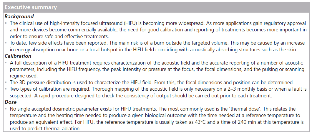
A full description of HIFU treatments requires characterization of the acoustic field and accurate reporting of a number of parameters. This is needed so that clinical safety can be maintained by appropriate selection of treatment parameters and, of particular importance in an emerging field, so that comparisons can be made between different patients treated on one device and between treatments carried out on different devices. To date, no standard protocols exist for either the description of a HIFU field or for its measurement.
Dose
The speciality of medical ultrasound suffers from a lack of dosimetric parameters. For x-irradiation, there is a differentiation between ‘exposure’, defined as a Roentgen in terms of the amount of ionization produced in air, which describes the amount of energy reaching the body and does not describe the fraction of incident energy that is absorbed within tissue, and ‘absorbed dose’, which is the amount of energy deposited in the tissue per kilogram, in gray and rad. No such distinction exists for ultrasound, and the terms exposure and dose are used interchangeably in the literature. The parallel here is that exposure describes the acoustic field incident on the tissue volume of interest, but does not provide information about the energy absorbed (the dose). HIFU exposures are usually described in terms of intensity (acoustic energy flux) or power. As the primary aim of the technique is thermal ablation, apart from the frequency, the most important feature of the HIFU beam is the total energy deposited in the target volume. This can be described in terms of the focal peak intensity and focal dimensions, as well as the exposure time, and a description of the pulsing and scanning regimes (where appropriate). Where acoustic cavitation may be involved, it is also important to know the spatial pressure distribution and to quote the peak negative pressure. Practically, the values of these parameters given are those obtained from measurements made in large, reflection-free water tanks under 'freefield' conditions. In order to calculate the actual exposure in the tissues of interest, the acoustic properties of tissue (attenuation and absorption coefficients) must be known. In practice, generic values of these coefficients taken from the literature are usually used.
An alternative method of describing HIFU treatments is to use the concept of thermal dose (tREF). This is commonly quoted for MRgHIFU treatments. Thermal dose, which is sometimes referred to as cumulative effective minutes (CEMREF) or the thermal isoeffective dose (TID), is designed to allow comparison of time–temperature combinations of one thermal treatment with a treatment that produces the same biological effect at a reference temperature, usually taken to be 43°C; t43 is given by:
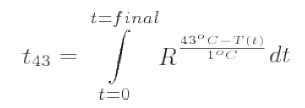
where R is the number of minutes needed to compensate for a 1°C temperature change either above 43°C (R = 0.5) or below 43oC (R = 0.25) [1]. Thermometry sequences are used to calculate the thermal dose that is displayed as an overlay on the anatomical image during MRgHIFU. The accuracy with which the thermal dose can be calculated depends on that of the temperature estimation, which is necessarily a compromise between spatial and temporal resolution. Ablation is deemed to have occurred when t43 is 240 min. There are a number of limitations to the use of thermal dose. It has not been fully validated for the temperature ranges important to HIFU treatments (>56°C), and does not take into account mechanical effects arising from acoustic cavitation and boiling, or previous exposures that may result in thermotolerance.
Other dosimetric descriptors have been put forward. These include the product of intensity and time, and the energy deposited per unit mass (equivalent to the specific absorption rate [SAR], which is used for other thermal therapies) [41–42]. However, none of these are able to account for the contribution to tissue damage of the mechanical effects of cavitation. A separate 'cavitation dose' has been proposed for this [43]. This is the integral of the broadband signal emitted during inertial cavitation (with the fundamental and any harmonic peaks filtered out) and has been shown, under some circumstances, to correlate well with cell survival [44–45]. While some commercial HIFU devices are capable of detecting cavitation activity, this information is not used to calculate any form of dose, but is, instead, used as an internal safety check for the device's drive software. USgHIFU systems define successful ablation in terms of the appearance of hyperecho on the ultrasound scan, indicating the occurrence of boiling bubbles. This is not used in any dosimetric sense.
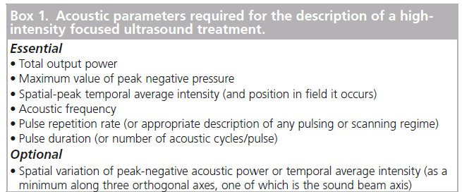
Duck has suggested the use of the acoustic dose rate. He defined two forms of this, one that describes heating due to the direct absorption of acoustic energy and one associated with cavitation-mediated heating [42]. The two are not combined and take no account of the mechanical effects described above. To date, no satisfactory dose parameter that fully describes the biological effects of an ultrasound exposure has been established and, at present, a full description of the incident acoustic field, measured in water, may provide the best way of describing a HIFU treatment. The parameters necessary for a full description of a HIFU treatment are shown in Box 1. This has been discussed by ter Haar et al. [46].
Calibration of HIFU fields
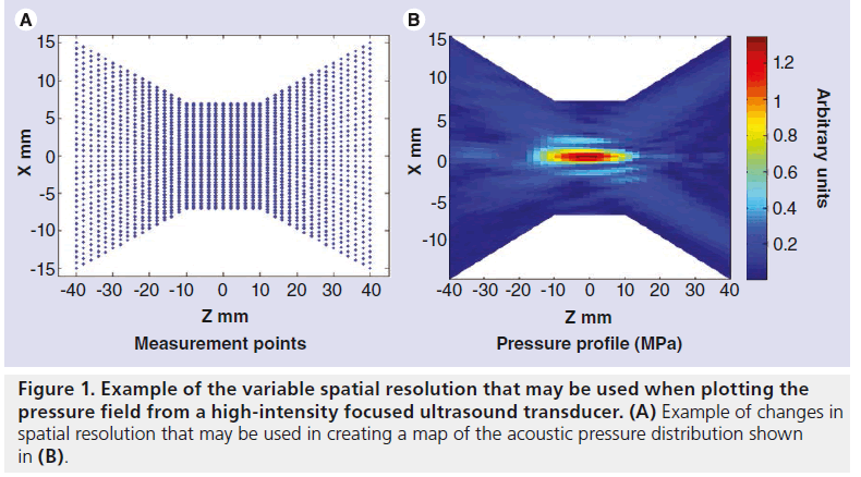
The most usual practical characterization of an acoustic field involves the mapping of the pressure distribution in 3D. It is often sufficient to change the separation of measurement points according to the region of the field being interrogated, with a higher spatial resolution being needed in the focal region and near any sidelobes and a lower resolution being sufficient elsewhere (Figure 1). There is no direct method of measuring intensity, and it is generally calculated using the expression

where p is the pressure amplitude, ρ is the density and c is the speed of sound. Thus, p2 distribution reflects the intensity distribution. For HIFU, the pressure (intensity) distribution is used to derive the focal dimensions, usually quoted in terms of the full width and half length at half pressure. Acoustic power may either be measured directly, as described below, or may be derived by integration of the intensity over the required area.
Calibration of clinical HIFU fields presents particular challenges [47]. The high peak pressure amplitudes used (up to 10 MPa) mean that cavitation in the coupling medium is difficult to avoid. Cavitation bubbles may shield the sensor from recording the true acoustic pressure or may destroy the element itself. The high intensities in these fields may result in heating of the hydrophone element, which risks damaging the element itself, and may change the sensitivity of the probe. The tight focusing seen in HIFU beams requires good spatial resolution if the focal shape is to be correctly registered. This requires a small sensitive volume for the hydrophone element. The directivity of a hydrophone must also be taken into account here. In the focal region, the plane wave assumption used to relate the acoustic pressure to intensity is no longer valid, and this results in errors in exposure reporting. The focal geometry must also be taken into account in order to perform accurate radiation force balance measurements.
High-amplitude acoustic pulses propagate nonlinearly in water, resulting in a distortion of the wave and the generation of harmonics of the fundamental frequency. The harmonic content at any point in the field can be measured using a calibrated hydrophone, provided that the frequency response of the hydrophone is known. As the acoustic attenuation coefficient of water is proportional to the frequency squared, these harmonics are absorbed more rapidly than the fundamental, leading to ‘nonlinear loss’ and, eventually, to ‘acoustic saturation’, where any change in the acoustic pressure generated at the transducer is not seen at the measurement point in the field [48]. This means that, for radiation force balance measurements, the incident power is strongly dependent on the distance at which the measurement is made. For hydrophone measurements in water, although acoustic saturation and nonlinear loss are not strictly a problem, care is necessary when extrapolating from measurements in water to values in tissue, where the nonlinear properties and attenuation coefficients are different.
Measurement techniques
Measurement of pressure
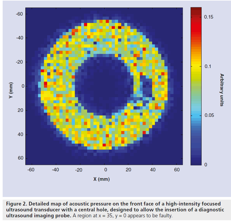
The instrument most commonly used to measure pressure in ultrasound fields is an acoustic hydrophone with a piezoelectric sensitive element that responds to the acoustic field, giving a voltage that depends on the local pressure amplitude. These sensors can be scanned through the field to give the pressure. The elements may be piezoor piezo-electric membranes (polyvinylidene difluoride) and are often mounted on the end of a needle. Wide-area membrane hydrophones with a small central sensitive element can also be used. These have the advantage that they do not interfere with the field they are intended to measure, but are only suitable for field measurements where sufficient space is available, such as in large water baths. The shaft of needle hydrophones may interact with the field if not used with care, but they are suitable for use in confined spaces. Pressure fields may also be measured using fiberoptic hydrophones. Two types of hydrophone are most commonly used: the hydrophone invented by Staudenraus and Eisenmenger [49] uses a thin optical fiber down which an infrared laser beam is passed. When the bare end of the fiber is submerged in fluid, usually water, light reflected at the fiber–fluid interface and transmitted back to the top of the fiber is detected by a photodiode via a directional fiber coupler. When the fluid density is altered by the passage of an ultrasound pulse, the reflected light intensity is modulated in proportion to the acoustic pressure. More recently, hydrophones in which a Fabry–Pérot polymer film interferometer is bonded to the tip of an optical fiber have been used [50]. The change in thickness of the film caused by the acoustic pressure, changes the optical signal amplitude. Hydrophones can be used where space is restricted and only minimally interfere with the field they are measuring. Fabry–Pérot hydrophones are capable of simultaneous temperature and pressure measurement [50,51]. The detail required in an acoustic pressure map depends on what it is going to be used for. Point-by-point measurements are time consuming, but it is possible to vary the spatial separation throughout the field, capturing fine detail only in regions where the pressure varies rapidly, such as in the focal region. The use of a small sensor, such as the fiber optic hydrophone, may allow pressure mapping close to the transducer face. This may reveal regions of the probe surface that are not functioning properly (Figure 2). The pressure at the transducer front face can also be obtained by measuring the field in a single plane perpendicular to the beam axis and using back propagation techniques to obtain the distribution (acoustic holography) [52].
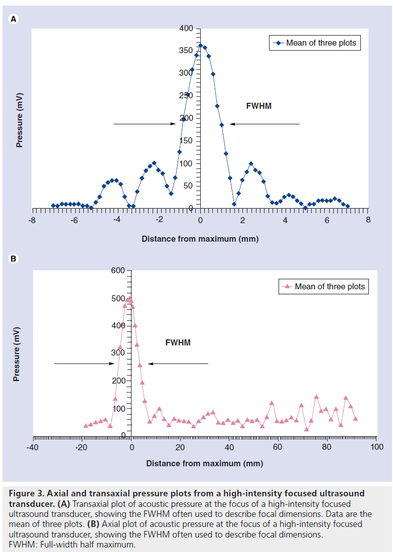
The important parameters to capture from the pressure plot are the focal dimensions (6 dB beam width), focal peak pressure, and the amplitude and position of any hot spots (or side lobes) (Figure 3). The intensity distribution can be derived by plotting the pressure amplitude squared.
Measurement of acoustic power
An ultrasound wave has an associated momentum and a target placed in its path will, therefore, experience a 'radiation force'. This can be used to measure acoustic power if the target is connected to an appropriate force-measuring device (e.g., a weighing balance). A weight change of 69 mg is produced by 1 W of power. These radiation force balances require targets large enough to encompass the whole beam [53,54]. An alternative method of determining power is to use its heating capability to change the buoyancy of an absorbing (castor oil) target [55]. If no hydrophone is available, then a measurement of total power can be used to infer the spatial peak intensity if assumptions are made about the beam shape.
Calibration of clinical devices
While it is feasible to characterize HIFU fields with reasonable accuracy (∼10%) when the transducers can be freely mounted in large water baths, the calibration of clinical HIFU sources in situ presents a more demanding challenge. A number of source geometries are used clinically. Large spherical bowl sources (with focal lengths of 10–15 cm and f-number of ∼1) comprised of a single element or multielement array, mounted in a water bath situated below a bed, and with acoustic coupling to the patient through either an intact membrane or a free water surface, are most commonly used for extracorporeal treatment of abdominal organs [56–58]. These operate at frequencies of approximately 1 MHz. Prostate treatments are usually carried out using a truncated bowl transducer (focal length: 3–4.5 cm) mounted on a transrectal probe similar to that used for diagnostic transrectal ultrasound examinations. These devices use high-frequency HIFU for ablative therapy (3 MHz for Ablatherm® [59] and 4 MHz for Sonablate® [60]), which results in small focal regions (e.g., 19–26 mm long × 1.7 mm). HIFU systems designed for brain exposures are comprised of very large hemispherical arrays (∼30 cm in diameter with a frequency of 670 kHz) and with 512–1024 individual elements. These have very small focal regions (2-mm wide and 4-mm long) so that the brain can be selectively targeted. The smaller devices designed for specific applications, such as those for the treatment of the breast and thyroid, may prove to be easier to characterize as the HIFU sources are essentially handheld and lend themselves most readily to laboratory-based calibration methods [21].
Figure 2.Detailed map of acoustic pressure on the front face of a high-intensity focused ultrasound transducer with a central hole, designed to allow the insertion of a diagnostic ultrasound imaging probe. A region at x = 35, y = 0 appears to be faulty.
Figure 3.Axial and transaxial pressure plots from a high-intensity focused ultrasound transducer. (A) Transaxial plot of acoustic pressure at the focus of a high-intensity focused ultrasound transducer, showing the FWHM often used to describe focal dimensions. Data are the mean of three plots. (B) Axial plot of acoustic pressure at the focus of a high-intensity focused ultrasound transducer, showing the FWHM often used to describe focal dimensions. FWHM: Full-width half maximum.
Most clinical users will need to rely on the manufacturer's information about the free-field pressure distribution from the HIFU source. Without specialist equipment, this is difficult to verify. The total acoustic power is somewhat easier to determine. While the majority of acoustic power measurement devices require the transducer to be placed above the target, it is possible to design systems in which the acoustic field is incident from below, thus allowing them to be used on current clinical extracorporeal systems. While there is no such commercial device available, some manufacturers provide their own version. Where this is not done, the user is advised to consult an appropriate medical physics or engineering specialist.
There are two main categories of calibration requirement. A 'quick-and-easy' procedure may be used prior to each treatment to address the question “am I giving the same treatment as I did yesterday/last week/last month?” (i.e., has there been a change in the system output that needs to be investigated) and a more thorough procedure designed to provide the user with detailed information about the absolute levels of acoustic output and the behavior of the device. While the former procedure can be carried out by a nontechnical specialist, the latter requires expert knowledge and, in the absence of any indication of a problem from the quick-andeasy technique, will not be necessary very often (e.g., every 20 treatments).
The rapid check may be carried out in a number of ways; although no commercial devices are currently available to achieve this. A simple, practical way is to use an infrared camera to image the heating distribution when the HIFU beam is incident on an absorber, such as a thin sheet of plastic placed on the surface of an acoustic couplant [61–63]. Other methods may involve scanning a hydrophone or thermally sensitive element rapidly through the field to locate the focal maximum and ensuring that this remains a constant between sessions, to within the measurement accuracy.
One aspect of calibration that cannot be overlooked in clinical applications is a check that the representation of the focal region used for targeting treatments coincides spatially with the true focal region. Under MR guidance, this can be carried out by using a low-power single-shot in ex vivo tissue or tissue-mimicking gel, and checking its position using the thermometry sequence. This is not that simple for US-guided systems. A temperature or pressure sensor embedded in a tissue mimic, targeted under imaging guidance using the integrated diagnostic probe, will allow users to check whether the maximum temperature (or pressure) amplitude coincides with the highlighted focal region. Backscatter temperature imaging or acoustic radiation force imaging may also be used to indicate the position of the target if a low-power siting shot is used [64,65].
Conclusion & future perspective
There is currently no universally accepted method of HIFU calibration. The International Electrotechnical Commission (IEC) is working on standards for high-intensity therapeutic ultrasound (HITU), which includes both focused and unfocused fields. These standards will cover output power measurement, and specification and measurement of field parameters for HITU transducers and systems, and particular requirements for basic safety and essential performance of HITU systems. This effort is essential because, while IEC standards have no force in law, they are likely to form the basis of national and international regulations. The required technology largely exists, but considerable effort is still required to adapt it for use with the increasing number of available clinical devices and geometries.
It will be important for the safety and credibility of HIFU treatments that instruments for field characterization and calibration become more readily available. These must give values that are traceable to primary standards. Equipment designated for a rapid assessment of the HIFU output prior to each treatment must be designed such that nontechnical experts can also use them.
It is to be hoped that, in parallel with improvements in HIFU calibrations, a consensus may be reached about dosimetry in this field. Without this, it will continue to be difficult to interpret HIFU treatments and to reproduce them between centers. This can only be detrimental to HIFU's progress towards acceptance as a first-choice clinical procedure for many applications. There is a European effort in this area, through an EU funded EURAMET project (Dosimetry for Ultrasound Therapy [DUTy]), involving standards institutes from the UK, Germany, Spain, Italy and Turkey, and researchers from Russia and the USA.
Financial & competing interests disclosure
The author has no relevant affiliations or financial involvement with any organization or entity with a financial interest in or financial conflict with the subject matter or materials discussed in the manuscript. This includes employment, consultancies, honoraria, stock ownership or options, expert testimony, grants or patents received or pending, or royalties.
No writing assistance was utilized in the production of this manuscript.
References
Papers of special note have been highlighted as:
* of considerable interest
- Sapareto DG, Dewey WC. Thermal dose determination in cancer therapy. Br. J. Radiat. Oncol. Biol. Phys. 10(6), 787– 800 (1984). nn Seminal paper that laid the foundations for the thermal dose currently used to characterize MR-guided high-intensity focused ultrasound treatments.
- Dewhirst MW, Viglianti BL, Lora-Michiels M, Hanson M, Hoopes PJ. Basic principles of thermal dosimetry and thermal thresholds for tissue damage from hyperthermia. Int. J. Hyperthermia 19, 267–294 (2003).
- ter Haar GR, Coussios CC. HIFU physical principles and devices. Int. J. Hyperthermia 23, 89–104 (2007).
- Martin E, Werner B. Focused ultrasound surgery of the brain. Curr. Radiol. Rep.1(2), 126–135 (2013).
- Martin E, Jeanmonod D, Morel A, Zadicario E, Werner B. High-intensity focused ultrasound for noninvasive functional neurosurgery. Ann. Neurol. 66, 858–861 (2009).
- Jun SB. Ultrasound as a noninvasive neuromodulation tool. Biomed. Eng. Lett. 2, 8 (2012).
- Marsac L, Chauvet D, Larrat B et al. MR-guided adaptive focusing of therapeutic ultrasound beams in the human head. Med. Phys. 39, 1141–1149 (2012).
- McDannold N, Clement GT, Black P, Jolesz F, Hynynen K. Transcranial magnetic resonance imaging – guided focused ultrasound surgery of brain tumors: initial findings in 3 patients. Neurosurgery 66, 323–332 (2010). & First paper to describe the clinical application of high-intensity focused ultrasound in the brain
- Froeling V, Meckelburg K, Scheurig-Muenkler C. Midterm results after uterine artery embolization versus MR-guided high-intensity focused ultrasound treatment for symptomatic uterine fibroids. 36(6), 1508–1513 (2013).
- Voogt MJ, van Stralen M, Ikink ME. Targeted vessel ablation for more efficient magnetic resonance-guided high-intensity focused ultrasound ablation of uterine fibroids. Cardiovasc. Intervent. Radiol. 35(5), 1205–1210 (2012).
- Wijlemans JW, Bartels LW, Deckers R et al. Magnetic resonance-guided high-intensity focused ultrasound (MR-HIFU) ablation of liver tumours. Cancer Imaging 12(2), 387 (2012).
- Cheung TT, Poon RTP, Yau T, Tsang DSF, Lo CM, Fan ST. High-intensity focused ultrasound as a treatment for colorectal liver metastasis in difficult position. Int. J. Colorectal Dis. 27(7), 987–988 (2012).
- Cheung TT, Chu FS, Jenkins CR et al. Tolerance of high-intensity focused ultrasound ablation in patients with hepatocellular carcinoma. World J. Surg. 36(10), 2420–2427 (2012).
- Cheung TT, Chok KS, Lo RC et al. Highintensity focused ultrasound ablation as a bridging therapy for hepatocellular carcinoma patients awaiting liver transplantation. Hepatobiliary Pancreat. Dis. Int. 11(5), 542–544 (2012).
- Leslie T, Ritchie R, Illing R et al. High intensity focused ultrasound treatment of liver tumours: post-treatment MRI correlates well with intra-operative estimates of treatment volume. Br. J. Radiol. 85(1018), 1363–1370 (2012).
- Illing RO, Kennedy J E, Wu F et al. The safety and feasibility of extracorporeal high-intensity focused ultrasound (HIFU) for the treatment of liver and kidney tumours in a Western population. Br. J. Cancer 93(8), 890–895 (2005).
- Margreiter M, Marberger M. Focal therapy and imaging in prostate and kidney cancer: high-intensity focused ultrasound ablation of small renal tumors. J. Endourol. 24(5), 745–748 (2010).
- de Senneville BD, Ries M, Bartels LW, Moonen CT. MRI-guided high-intensity focused ultrasound sonication of liver and kidney. In: Interventional Magnetic Resonance Imaging. Springer, Berlin Heidelberg, Germany, 349–366 (2012).
- Ritchie RW, Leslie T, Phillips R et al. Extracorporeal high intensity focused ultrasound for renal tumours: a 3-year follow-up. Br. J. Urol. Int. 106( 7) 1004– 1009 ( 2010).
- Orgera G, Krokidis M, Monfardini L et al. Ultrasound-guided high-intensity focused ultrasound (USgHIFU) ablation in pancreatic metastasis from renal cell carcinoma. Cardiovasc. Intervent. Radiol. 35(5), 1258–1261 (2012).
- Diaz R. Thyroid: HIFU for thyroid nodule ablation. Nat. Rev. Endocrinol. 7(11), 631–631 (2011).
- Esnault O, Franc B, Ménégaux F et al. High-intensity focused ultrasound ablation of thyroid nodules: first human feasibility study. Thyroid 21(9), 965–973 (2011).
- Merckel LG, Bartels LW, Köhler MO. MR-guided high-intensity focused ultrasound ablation of breast cancer with a dedicated breast platform. Cardiovasc. Intervent. Radiol. 36(2), 292–301 (2012).
- Orgera G, Curigliano G, Krokidis M et al. High-intensity focused ultrasound effect in breast cancer nodal metastasis. Cardiovasc. Intervent. Radiol. 33(2), 447–449 (2010).
- Postma EL, van Hillegersberg R, Daniel BL, Merckel LG, Verkooijen HM, van den Bosch MA. MRI-guided ablation of breast cancer: where do we stand today? J. Magn. Reson. Imaging 34(2), 254–261 (2011).
- Gillies MJ, Bojanic S, Ritchie R, Leslie T. High intensity focused ultrasound (HIFU) for recurrent sacrococcygeal chordoma. J. Bone Joint Surg. 94(Suppl. XXVI), 50– 50 (2012).
- Serrone J, Kocaeli H, Mast T Douglas, Burgess MT, Zuccarello M. The potential applications of high-intensity focused ultrasound (HIFU) in vascular neurosurgery. J. Clin. Neurosci. 19(2), 214–221 (2012).
- Griffiths A, Rivens I, Giussani D, Lees C. High-intensity focused ultrasound in obstetrics and gynecology: the birth of a new era of noninvasive surgery? Ultraschall Med. 33(7), E8–E15 (2012).
- Ichizuka K, Hasegawa J, Nakamura M et al. High-intensity focused ultrasound treatment for twin reversed arterial perfusion sequence. Ultrasound in Obstetrics & Gynecology, 40(4), 476–478 (2012).
- Cordeiro ER, Cathelineau X, Thüroff S, Marberger M, Crouzet S, de la Rosette JJ. High-intensity focused ultrasound (HIFU) for definitive treatment of prostate cancer. BJU Int. 110(9), 1228–1242 (2012).
- Gelet A, Crouzet S, Rouviere O, Chapelon JY. High-intensity focused ultrasound (HIFU) for prostate cancer. In: Management of Prostate Cancer. Springer, Berlin Heidelberg, Germany, 191–212 (2012).
- Uchida T, Nakano M, Shoji S, Nagata Y, Usui Y, Terachi T. Twelve years’ experience with high-intensity focused ultrasound (HIFU) using sonablate™ devices for the treatment of localized prostate cancer. AIP Conf. Proc. 1481, 401 (2012).
- Dickinson P, Sundar S. Salvage radiotherapy after high intensity focused ultrasound for prostate cancer. BMJ Case Rep. doi:10.1136bcr.03.2012.6127 (2012) (Online).
- Blana A, Robertson CN, Brown SCW, Complete high-intensity focused ultrasound in prostate cancer: outcome from the @-Registry. Prostate Cancer and Prostatic Diseases 15(3), 256–259(2012).
- Ahmed HU, Freeman A, Kirkham A et al. Focal therapy for localized prostate cancer: a Phase I/II trial. J. Urol. 185(4), 1246–1255 (2011).
- ter Haar GR, Robertson D. Tissue destruction with focused ultrasound in vivo. Eur. Urol. 23(Suppl.1), 8–11 (1993).
- McLaughlan J, Rivens I, ter Haar G. A study of acoustic cavitation and boiling in ex vivo tissue exposed to high intensity focused ultrasound (HIFU). Ultrasound Med. Biol. 36, 1327–1344 (2010).
- Cheung TT, Chu FS, Jenkins CR et al. Tolerance of high-intensity focused ultrasound ablation in patients with hepatocellular carcinoma. World J. Surg. 36(10), 2420–2427 (2012).
- Leon-Villapalos J, Kaniorou-Larai M, Dziewulski P. Full thickness abdominal burn following magnetic resonance-guided focused ultrasound therapy. Burns 31, 1054–1055 (2005).
- Fry WJ, Mosberg WH, Barnard JW, Fry FJ. Production of focal destructive lesions in the central nervous system with ultrasound. J. Neurosurg. 11, 471–478 (1954).
- Fry FJ, Kossoff G, Eggleton RC, Dunn F. Threshold ultrasonic dosages for structural changes in the mammalian brain. J. Acoust. Soc. Am. 48, 1413 (1970).
- Duck F. Acoustic dose and acoustic dose-rate. Ultrasound Med. Biol. 35(10), 1679–1685 (2009). nn Outlines a number of potential methods for describing high-intensity focused ultrasound dose.
- Chen WS, Brayman AA, Matula TJ, Crum LA. Inertial cavitation dose and hemolysis produced in vitro with or without Optison®. Ultrasound Med. Biol. 29(5), 725–737 (2003).
- Chen WS, Brayman AA, Matula TJ, Crum LA, Miller MW. The pulse lengthdependence of inertial cavitation dose and hemolysis. Ultrasound Med. Biol. 29(5), 739–748 (2003).
- Hallow DM, Mahajan AD, McCutchen TE, Prausnitz MR. Measurement and correlation of acoustic cavitation with cellular bioeffects. Ultrasound Med. Biol. 32(7), 1111–1122 (2006).
- ter Haar G, Shaw A, Pye S et al. Guidance on reporting ultrasound exposure conditions for bio-effects studies. Ultrasound Med. Biol. 37(2), 177–183 (2011). & Guidelines for the description of ultrasound exposures.
- Shaw A, ter Haar G. Requirements for Measurement Standards in High Intensity Focused Ultrasound (HIFU) Fields. National Physical Laboratory, Teddington, UK (2006).
- Duck FA. Acoustic saturation and output regulation. Ultrasound Med. Biol. 25(6), 1009–1018 (1999).
- Staudenraus J, Eisenmenger W. Fiber-optic probe hydrophone for ultrasonic and shock-wave measurements in water. Ultrasonics 31(4), 267–273 (1993).
- Beard PC, Mills TN. Miniature optical fiber ultrasonic hydrophone using a Fabry–Pérot polymer film interferometer. Electrons Lett. 33(9), 801–803 (1997).
- Morris P, Hurrell A, Shaw A, Zhang E, Beard P. A Fabry–Pérot fiber-optic ultrasonic hydrophone for the simultaneous measurement of temperature and acoustic pressure. J. Acoust. Soc. Am. 125, 3611 (2009).
- Kreider W, Sapozhnikov O A, Farr N. Acoustic holography and nonlinear modeling methods to characterize the Philips MR-guided HIFU source. Presented at: 11th International Symposium on Therapeutic Ultrasound. NY, USA, 10–12 April 2011.
- Beissner K, Oosterbahn WA, Hekkenberg RT, Shaw A. European intercomparison of ultrasonic power measurement. Acustica 82, 450–458 (1996).
- Zeqiri B. Metrology for ultrasonic applications. Prog. Biophys. Mol. Biol. 93(1–3), 138–152 (2007).
- Shaw A. A buoyancy method for the measurement of total ultrasound power generated by HIFU transducers. Ultrasound Med. Biol., 34(8), 1327–1342 (2008).
- MR guided focused ultrasound surgery (MRgFUS): what is it? www.insightec.com/MRgFUS-Technology. html
- Creating the future forMR-HIFU. www.healthcare.philips.com/main/products/ mri/systems/sonalleve/
- Haifu®. www.haifu.com.cn/en_index.asp
- Ablatherm® HIFU. www.edap-tms.com/products-services/ ablatherm-hifu
- Sonablate® 500. http://sonacaremedical.com/sonablate-500- high-intensity-focused-ultrasound
- Hand JW, Shaw A, Sadhoo N, Rajagopal S, Dickinson R, Gavrilov LR. A random phased array device for delivery of high intensity focused ultrasound. Phys. Med. Biol. 54, 5675–5693 (2009).
- Bobkova S, Gavrilov L, Khokhlova V, Shaw A, Hand J. Focusing of high-intensity ultrasound through the rib cage using a therapeutic random phased array. Ultrasound Med. Biol. 36, 888–906 (2010).
- Shaw A, Nunn J. The feasibility of an infrared system for real-time visualization and mapping of ultrasound fields. Phys. Med. Biol. 55, 321–327 (2010).
- Civale J, Bamber J, Miller N, Rivens I, ter Haar G. Attenuation estimation and temperature imaging using backscatter for extracorporeal HIFU treatment planning. AIP Conf. Proc. 911, 14 (2007).
- Lizzi FL, Muratore R, Deng CX et al. Radiation-force technique to monitor lesions during ultrasonic therapy. Ultrasound Med. Biol. 29(11) 1593–1605 (2003).
